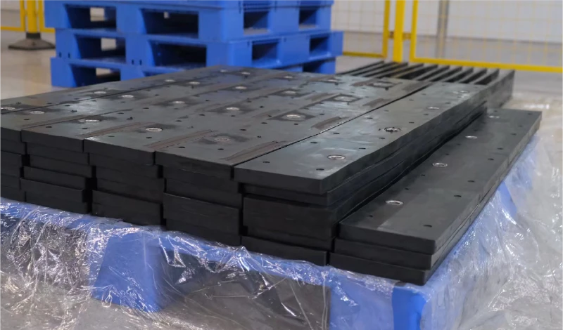
For joma 6000 blades and cutting edges: fitment, segments and replacement, the best result comes from matching the component, material, and setup to a documented operating condition, then validating fit, wear, safety, and cost in a controlled trial. This updated guide uses current search evidence and official-source checks to turn the topic into a repeatable selection process.
Updated: October 19, 2026
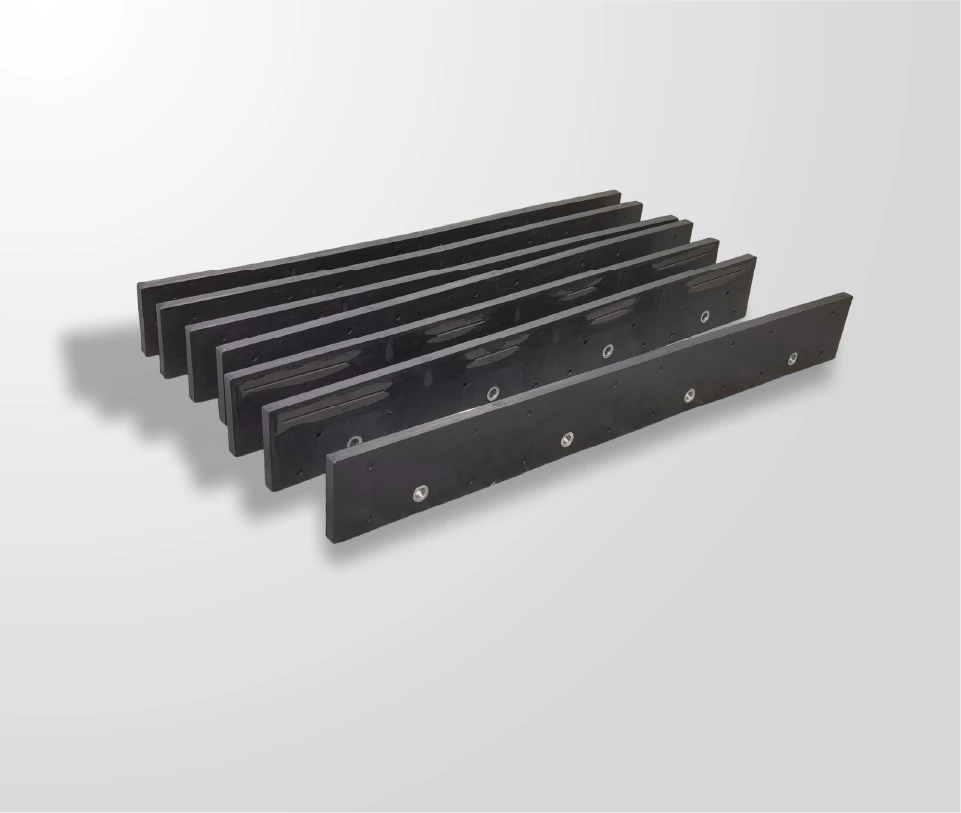
Three figures decide whether a replacement fits: the hole pattern measured on the moldboard, the segment length that covers the remaining width, and the overall length the carrier accepts. Most fitment failures come from ordering against a family name instead of those three, and the part that arrives cannot be made to work however carefully it is installed.
What follows works backwards from that failure — an edge that does not fit — to the checks that prevent it, then forward through the replacement itself and the spares worth holding.
What the 6000 designation refers to
It identifies a family, not a fixed part.
The 6000 designation places a blade in the JOMA style range; length, segment layout and hole pattern vary within the family and have to be confirmed before ordering.
Treating the designation as a complete description is the origin of most fitment problems, because two blades in the same family can be built for different moldboard widths and different mounting patterns. What the family does establish is the construction: a flexible base carrying carbide wear segments, with the segment layout designed to be replaced section by section rather than as a whole edge. Everything the buyer needs beyond that — length, thickness, hole spacing, hole diameter and segment count — comes from measuring the machine.
The practical consequence is that the designation belongs in the conversation but not in the order on its own. A supplier who receives only a family name has to guess at the rest, and the guess is what produces a blade that arrives, does not fit and has to be returned. The construction detail is described on the JOMA style blade page.
What to measure before you quote the designation
Five measurements describe the blade a machine needs, and they are all taken on the moldboard rather than on the worn edge. Working in this order avoids the compounding error of measuring a part that was already wrong when it was fitted.
- Blade length along the mounting edge, measured on the moldboard.
- Hole diameter, measured in two holes rather than one.
- Hole spacing centre to centre, measured at both ends and in the middle.
- The distance from the top edge of the blade to the hole centres.
- The available width for segments, which sets how the length divides.
The last item is the one that decides the segment count, and it is the measurement most often skipped. A blade whose width divides evenly into the available segment lengths needs fewer joints than one where the remainder has to be absorbed at one end.
Common mounting patterns
Mounting patterns fall into families as well, and the pattern is what the replacement has to match before anything else matters. Differences appear in hole diameter, in the distance between holes, and in the form of the hole itself where a countersunk fixing is used.
Two rules keep the check reliable. Measure the pattern on the machine rather than on the edge being replaced, because a worn edge may have been re-drilled or may never have fitted properly. And record the hole form as well as the diameter: a countersunk hole and a plain hole accept different hardware, and a blade supplied for the wrong one will either carry a proud head or fail to seat at all.
| Detail | Why it varies | How to check it |
|---|---|---|
| Hole diameter | Bolt size differs between blade classes | Measure two holes with a caliper or gauge |
| Hole spacing | Pitch follows blade length and manufacturer | Measure centre to centre at both ends and the middle |
| Hole form | Countersunk and plain holes take different fixings | Look at the seat, not only the hole |
| Distance from the top edge | Sets how the blade sits on the moldboard | Measure from the mounting face to the hole centres |
Segment lengths and bolt layouts
Segment length decides the number of joints, the weight of each piece handled at replacement, and how the blade’s length divides. The trade is the one described in the segment-length comparison: more joints mean more fixings to check and more places for movement to begin, while fewer, longer segments mean heavier pieces and a larger part to replace when one section is damaged.
The bolt layout follows the segment layout, and the two are specified together. Each joint needs its fixings either side, and the spacing within a segment is usually wider than the spacing across a joint. Ordering segments without confirming the bolt layout that goes with them is a common cause of a delivery that contains the right segments and the wrong hardware. The sizing decision itself is covered in 3 ft versus 4 ft JOMA segments.
Confirming fitment before ordering
Fitment confirmation is a short exchange with the supplier and it is worth completing in writing. The four items below are what a supplier needs to confirm a family blade against a specific machine, and all of them come from the measurements above.
- The measured hole pattern, including diameter and hole form.
- Blade length and the width available for segments.
- The carrier and mounting position, since a front blade and an underbody blade can share a pattern but not a load case.
- A photograph of the mounting with a tape measure along the hole line, which resolves most ambiguities about how the figures were taken.
Where a fleet runs several machines in the same family, the confirmation is worth doing once per pattern and keeping on file, because the next order for the same machine then needs only a quantity.
Replacement sequence step by step
Replacing segments is a workshop job that can be completed on the machine, and the sequence matters because the joint faces have to mate when the work finishes. Working from the centre outwards is what keeps the joints closed rather than pushing any gap towards one end of the blade.
- Park on level ground, lower the blade and secure the machine against movement.
- Inspect the mounting line and the faces of the segments that will stay in place.
- Remove the fixings at the joints of the segment being replaced, keeping the hardware with the segment.
- Clean the mating faces and the mounting line; grit under a joint is what lets it move.
- Fit the replacement segment, checking that its faces mate without force.
- Torque from the centre of the blade outwards, then re-check the joints after the first shift.
Step two is the one that turns a repair into a repair. Fitting a new segment between two damaged faces reproduces the failure within a few storms, and the evidence appears as movement at the joints rather than as wear on the new part.
Torque and hardware notes
The hardware on a segment blade is specified with the pattern, and substituting a similar-looking fixing changes the assembly quietly. Two details matter most: the head form, which must match the hole, and the grade, which decides how much torque the fixing will accept before it yields.
Torque itself is a function of diameter, grade and thread condition rather than of the position on the blade, so the value quoted by the supplier applies across the assembly. What changes at the joints is the check interval rather than the value: joint fixings carry more load and are worth re-checking after the first shift, when the assembly settles.
What arrives in a replacement order and how to check it
Receiving a segment order against the specification takes a few minutes and prevents a mid-season surprise. Four checks cover it, and each corresponds to a way an order can be wrong.
| Check | Method | Fault it detects |
|---|---|---|
| Segment count and length | Count and measure against the order | A layout that will not cover the blade width |
| Hole pattern | Measure two holes and the spacing at both ends | A pattern drilled for a different mounting |
| Hardware | Confirm head form, grade and quantity | Fixings that will not seat or will not hold torque |
| Faces | Check mating faces for flatness against a straight edge | A segment that will leave a joint open |
The check that pays for itself most often is the second. A pattern that is close but not correct cannot be corrected in the workshop without drilling a load-bearing part, and the delivery is far easier to resolve before the blade is dismantled.
Spares to keep on the shelf
The spares list for a segment blade follows the replacement practice rather than the catalogue: the segment lengths in use across the fleet, the hardware specified with each pattern, and the cleaning and measuring tools the job needs.
Two items are worth adding beyond the obvious. A straight edge, because it is the tool that confirms whether a joint can be closed and whether the mounting line is sound before any segment is removed. And a record of the settings and measurements from the last replacement, because the next one starts from those figures rather than from the machine as found. Equipment and mounting practice for these assemblies is published by the Association of Equipment Manufacturers, and component practice by AASHTO.
Winter maintenance guidance is published by the Federal Highway Administration, research by the Transportation Research Board, operator practice by the Snow and Ice Management Association, and material test methods by ASTM International.
SENTHAI manufactures JOMA style rubber-flex blades, replacement segments and cutting edges in Rayong, Thailand, and confirms the hole pattern and segment layout against the customer’s measurements before production. Replacement blades are listed under JOMA style replacement blades, and the full range is on the snow plow blade hub.
Use Measurements and Failure Modes Instead of a Fixed Replacement Rule
This research-backed framework closes a recurring gap in pages ranking for joma blade: readers need a decision method, not a list of unsupported superlatives. Apply the same evidence fields to every option before choosing joma 6000 blades and cutting edges: fitment, segments and replacement.
| Decision gate | Evidence to collect | Release rule |
|---|---|---|
| Geometry | Remaining edge height, bevel condition, straightness, and bolt-hole clearance | Replace before the holder, moldboard, or fasteners become the wear surface |
| Carbide retention | Missing, cracked, or loose inserts and braze-line separation | Remove a damaged section from service and identify the impact or bond cause |
| Machine behavior | Chatter, skipping, pull, vibration, and repeated readjustment | Check attack angle, down pressure, shoes, trip system, and carrier condition |
| Route evidence | Surface, speed, temperature, obstacles, hours, and operator notes | Compare like-for-like routes before changing edge material or bevel |
A single service-life number or bevel angle cannot be universal. Carrier geometry, attack angle, road surface, impact frequency, setup, and operator practice all change the result.
Run a Controlled Trial Before Full-Fleet Adoption
-
Freeze the baseline: record the current component, carrier settings, route, weather, operator, hours, and reason for removal.
-
Approve fit first: compare the supplier drawing with the machine and attachment. Do not drill, grind, weld, or substitute fasteners without an approved procedure.
-
Change one major variable: keep route and operating method as consistent as practical so the result can be attributed to the component rather than a different setup.
-
Inspect at planned intervals: photograph the same locations, measure wear, check fastener torque and retention, and log impacts or abnormal vibration.
-
Release against written criteria: decide in advance what wear, removal quality, downtime, and cost per operating hour would justify expansion.
Official-Source and SERP Verification
The technical boundary was checked against Federal Highway Administration snow and ice guidance. That source is used for the operating or safety context; model-specific dimensions, settings, and limits must still come from the approved manual for the exact machine and component. The following leading pages were reviewed for search intent and missing decision details:
Frequently Asked Questions
What should be verified before selecting joma 6000 blades and cutting edges: fitment, segments and replacement?
Confirm the exact application, dimensions, carrier limits, operating surface, expected impacts, supplier drawing, and acceptance evidence. A product name or grade label alone is not enough.
How should joma 6000 blades and cutting edges: fitment, segments and replacement be compared on cost?
Compare landed and installed cost, service hours, maintenance labor, downtime, collateral wear, and replacement reason. Use cost per operating hour for comparable routes rather than purchase price alone.
When is a trial required?
Use a controlled trial whenever fit, material, setup, route conditions, or supplier process changes. Define the baseline and pass criteria before the trial starts.
Which document controls installation and operating limits?
The current manual, approved drawing, and written instructions for the exact carrier and component control. General articles and cross-reference tables are screening tools, not installation authority.
Request an Application Review
Send SENTHAI the carrier or machine model, drawing or dimensions, operating surface, route condition, current failure mode, expected quantity, and target service interval. The engineering team can then review a suitable product path without changing the evidence requirements described above.