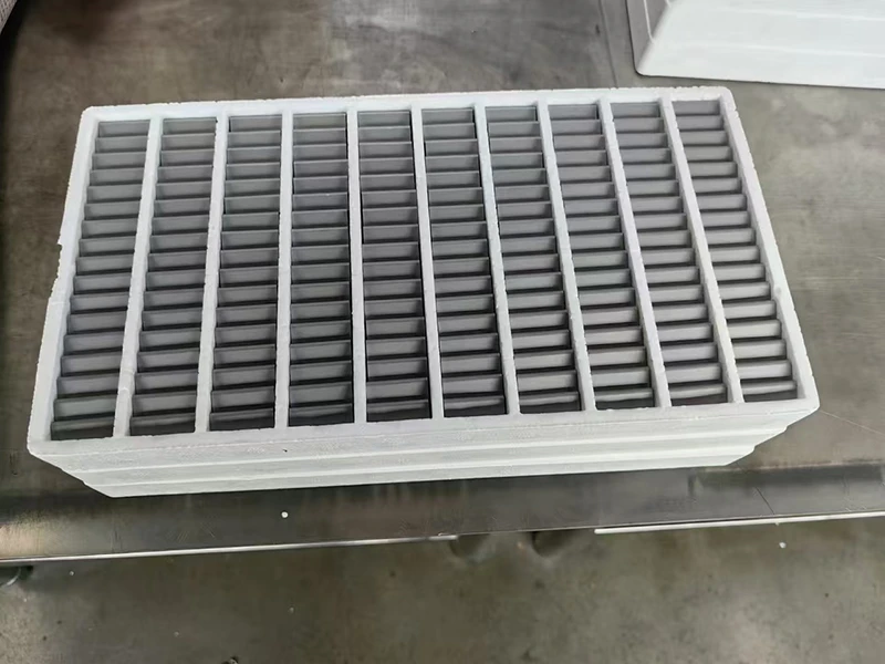
For carbide insert troubleshooting: chipping, pull-out and cracking, the best result comes from matching the component, material, and setup to a documented operating condition, then validating fit, wear, safety, and cost in a controlled trial. This updated guide uses current search evidence and official-source checks to turn the topic into a repeatable selection process.
Updated: October 19, 2026
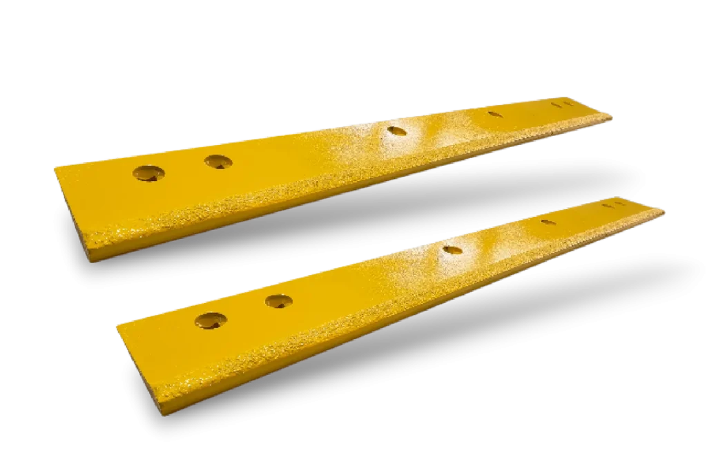
A new set of inserts chips through its first two weeks, the fleet assumes the grade is wrong, orders a tougher one, and the second set wears out before the season ends. The chipping was real, but it was not the grade: four positions at the end of the edge were standing proud on a mounting line that had been bowed by a previous impact, and they were taking every transition on the route.
Symptoms look similar and causes do not. This troubleshooting guide maps each visible failure to the causes that produce it, works through the ones that appear at particular points in an insert’s life, and closes on the evidence that makes a claim resolvable rather than arguable.
Carbide insert failure: reading the symptom before the cause
Chipping, cracking and pull-out cover most failures.
They look similar to an operator and point to different causes. Chipping is a load event, so the question is what delivered the load. Cracking is a strain event, so the question is what the insert was attached to and how it was loaded repeatedly.
Pull-out is a retention event, so the question is what the joint or the seat was doing before the insert left. Reading the symptom before ordering a replacement grade is what keeps a fleet from paying twice for the same problem.
The second reading that matters is position. A pattern concentrated at the ends of the working width, or beside a segment joint, or next to a fixing, describes a fitment cause. A pattern spread evenly along the row describes a material or duty cause. Two failures in the same place on two different edges are almost always a fitment story.
Symptom to cause mapping
The table below maps each visible symptom to the causes that produce it and the first check that rules each one in or out. It is intended as a starting point for a diagnosis rather than a substitute for one.
| Symptom | Typical causes | First check |
|---|---|---|
| Chipped corners concentrated at the ends | Impact at surface transitions, proud insert, bow in the mounting line | Straight-edge check along the mounting line |
| Chipping spread along the row | Grade too hard for the duty, down pressure too high | Previous season’s wear pattern and the machine’s down-pressure setting |
| Crack across the insert face | Thermal cycling, partially bonded joint, seat movement | Joint condition where the insert came from |
| Insert missing with filler on the steel | Joint moved before it failed, or the insert was never seated flat | The seat surface and the remaining joint footprint |
| Fretted seat, fixing still tight | Excess clearance in the pocket, load transferred to the fixing | Seat fit against the drawing tolerance |
The last row is the one most often read as a hardware problem. A fixing that is still at its specified tightness while the seat around it is polished has not failed; it has been carrying a load it was never meant to take.
Edge chipping on new edges
Chipping in the first weeks of a season is diagnostic because there has not yet been time for wear to change anything. A new insert that chips early has met something, or was installed in a condition that concentrated load onto it.
The two most common causes are visible from the machine. An insert standing proud because a seat was not fully cleaned, or because a partial replacement put new inserts beside worn ones, takes the first impact and transmits it into a much smaller area than the design intended. And a mounting line that is no longer straight loads the inserts on the high side harder, which produces chipping at positions that are consistently in the same place along the width.
Where neither is present, the duty itself has changed: a route that gained a section of new surface, a machine that has had its down pressure adjusted, or a season with more freeze-thaw cycles than the previous one. Those three show up as chipping distributed across the row rather than concentrated.
Mid-life cracking patterns
Cracking that appears in the middle of an insert’s life rather than at the beginning is a strain story rather than a load story, and the direction of the crack is the clue. A crack that runs across the insert, roughly perpendicular to the contact line, indicates repeated strain from thermal cycling or from a joint that is only partly bonded. A crack that runs back from the contact edge along the wear face is closer to a wear-fatigue mechanism and usually accompanies a grade that is at its limit for the duty.
The reason thermal and joint causes produce the same signature is that both put the material under strain it cannot distribute. In a fully bonded joint the strain spreads across the footprint; in a partly bonded one the bonded area carries it all, and the crack appears at the boundary. That is why changing grade rarely resolves this pattern, and why the joint condition is the first thing worth checking. The mechanisms behind loss of this kind are set out on the insert loss page.
Pull-out at the ends of a blade
The ends of a working width are the hardest place on the edge, and the reason is structural rather than metallurgical. They meet the most transitions: shoulder edges, driveway entrances, bridge joints and the pavement-to-gravel change that a route crosses several times a day, all at the point where the machine has the least consistent support.
An insert at the end of a row therefore sees impact at a leverage the joint was not sized for, and it starts moving before it is lost. Two design responses work: giving the end positions more lateral support so the load is carried into the steel, or specifying a tougher insert at the ends so the material survives the event that starts the movement. What does not work is closing the pitch at the ends to add support, because the resulting tight section then wears faster and the edge reports as uneven.
Failures linked to operator technique
Operator-related failures are real, and they are the ones most often used to close an investigation early. Four practices account for most of them: running with more down pressure than the surface requires, carrying speed through transitions rather than lifting, using the edge to break through material that should be bladed in stages, and backing up or turning with the edge in contact with the road.
The signature of an operator-related failure is timing and location rather than material. It appears shortly after a specific route or a specific driver joins the roster, it clusters at the transitions on that route, and it affects one machine rather than the fleet. That pattern is worth confirming before a grade is changed, because a grade change made for an operator cause will shorten the interval everywhere else.
Failures linked to fitment
Fitment causes produce the most repeatable patterns and are the easiest to eliminate with a measurement. A mounting line that has bowed, a fixing pattern with elongation at several consecutive positions, and a seat that no longer holds its insert all change the load distribution along the edge rather than at one point.
Two practical checks separate fitment failures from everything else. The first is to measure the mounting line along its length on a flat surface, which takes minutes and rules the question in or out. The second is to compare the positions that failed with the positions that wear fastest on a sound edge; where they coincide, the fitment is driving both. The tolerances that govern these fits are set out on the dimensional tolerance page.
Working back to a root cause
Running the diagnosis in a fixed order prevents the most common error, which is fixing the most visible cause rather than the actual one.
- Record where the failures are along the edge before anything is dismantled.
- Check the mounting line and the fixing pattern for distortion or elongation.
- Inspect the seat condition of every failed position, including the inserts that did not fail.
- Compare the pattern with the wear distribution from the previous season.
- Check the machine’s down pressure and the route changes since the last season.
- Only then consider a specification change, and change one variable at a time.
The sixth step is the discipline that makes the next season informative. Where a grade and a geometry change in the same order, neither can be evaluated, and the fleet is left with a better-feeling answer and no evidence.
Patterns that repeat across a fleet
Two patterns are worth naming because they change what the diagnosis means.
- The same position failing across several edges points to a route feature, a machine adjustment or a specification decision rather than to the material.
- Failures appearing across several batches within one season point to a duty or fitment change rather than to a production problem.
The second entry is the one that generates unnecessary claims. A material problem usually tracks the batch; a duty problem tracks the route. Recording the batch reference alongside the failure position is what lets those two be separated, and it costs one field on an inspection sheet.
What evidence to collect for a claim
A claim is resolved on evidence rather than on the number of inserts involved, and five items carry the argument. Record the position of each failure along the edge, the hours or lane-kilometres the set ran, the batch reference, photographs of the whole row and the end view, and the steel that each failed insert came out of.
The last item decides most cases. An insert that has left filler metal on the steel tells a different story from one that took the filler with it, and a supplier can usually read which happened in minutes if the seat is available. Brazing practice and the vocabulary for describing joint condition are published by the American Welding Society, and the test methods behind any material claim by ASTM International.
SENTHAI manufactures tungsten carbide inserts and plow edges in Rayong, Thailand, with each lot recorded against the drawing it was produced to, as described on the quality control page. Where a failure needs to be read rather than described, the diagnostic sequence used on returned inserts is set out on the wear pattern page, and failures that need to be assessed against a batch record can be raised through the contact page. Classification conventions for hardmetals are published by ISO, winter maintenance research by the Transportation Research Board, and fleet-level maintenance practice by the Snow and Ice Management Association.
Specify the Material and Acceptance Evidence Before Comparing Grades
This research-backed framework closes a recurring gap in pages ranking for Carbide Insert Troubleshooting: Chipping, Pull-Out and Cracking: readers need a decision method, not a list of unsupported superlatives. Apply the same evidence fields to every option before choosing carbide insert troubleshooting: chipping, pull-out and cracking.
| Decision gate | Evidence to collect | Release rule |
|---|---|---|
| Grade identity | Supplier grade, WC grain range, binder system, and lot number | Treat cross-reference charts as a shortlist, never automatic equivalence |
| Properties | Declared hardness, density, transverse-rupture or toughness evidence | Balance wear resistance against impact risk for the actual duty |
| Interface | Insert geometry, pocket fit, surface preparation, braze alloy, and gap control | A strong grade cannot compensate for poor fit or joining |
| Acceptance | Drawing, certificate, sampling plan, visual criteria, and destructive test where agreed | Approve the process and lot evidence, not only a sample photograph |
Hardness is only one screening value. Grade selection must also account for impact, thermal cycling, corrosion exposure, support geometry, joining quality, and the cost of an insert-loss failure.
Run a Controlled Trial Before Full-Fleet Adoption
-
Freeze the baseline: record the current component, carrier settings, route, weather, operator, hours, and reason for removal.
-
Approve fit first: compare the supplier drawing with the machine and attachment. Do not drill, grind, weld, or substitute fasteners without an approved procedure.
-
Change one major variable: keep route and operating method as consistent as practical so the result can be attributed to the component rather than a different setup.
-
Inspect at planned intervals: photograph the same locations, measure wear, check fastener torque and retention, and log impacts or abnormal vibration.
-
Release against written criteria: decide in advance what wear, removal quality, downtime, and cost per operating hour would justify expansion.
Official-Source and SERP Verification
The technical boundary was checked against Federal Highway Administration snow and ice guidance. That source is used for the operating or safety context; model-specific dimensions, settings, and limits must still come from the approved manual for the exact machine and component. The following leading pages were reviewed for search intent and missing decision details:
Frequently Asked Questions
What should be verified before selecting carbide insert troubleshooting: chipping, pull-out and cracking?
Confirm the exact application, dimensions, carrier limits, operating surface, expected impacts, supplier drawing, and acceptance evidence. A product name or grade label alone is not enough.
How should carbide insert troubleshooting: chipping, pull-out and cracking be compared on cost?
Compare landed and installed cost, service hours, maintenance labor, downtime, collateral wear, and replacement reason. Use cost per operating hour for comparable routes rather than purchase price alone.
When is a trial required?
Use a controlled trial whenever fit, material, setup, route conditions, or supplier process changes. Define the baseline and pass criteria before the trial starts.
Which document controls installation and operating limits?
The current manual, approved drawing, and written instructions for the exact carrier and component control. General articles and cross-reference tables are screening tools, not installation authority.
Request an Application Review
Send SENTHAI the carrier or machine model, drawing or dimensions, operating surface, route condition, current failure mode, expected quantity, and target service interval. The engineering team can then review a suitable product path without changing the evidence requirements described above.