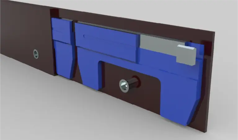
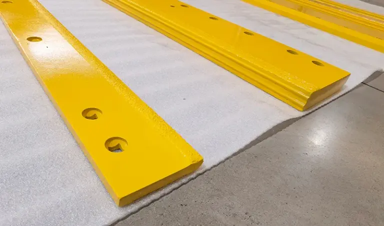
Size a weld-on edge from the mouldboard’s lower lip and the existing hole pattern, not from the nominal blade width. Measure the mounting height, the exposed wear depth you want to leave, and the hole pitch on the base angle; then match those to the weld-on edge drawing. The cutting edge length may run slightly wider than the mouldboard, but the hole spacing and weld line position must be exact.
Weld-on edges remove the bolt holes that normally allow adjustment, so the fit has to be correct before anyone strikes an arc. The dimensions that matter are the ones on the base angle and the mouldboard, not the sales literature. This note covers how to take those measurements and how to translate them into a specification you can order against.
Start from the mouldboard, not the box
The mouldboard’s lower lip sets the reference plane. Measure its straightness and its width before you measure anything else, because a bent or repaired lip will transfer that error into the weld-on edge. A short straightedge and a tape are enough for most pickup plows.
Record three things: the width of the lower lip across the plow, the vertical height available between the lip and the first obstruction (rib, gusset, or trip spring bracket), and the thickness of the base material the edge will weld to. These three numbers bound the edge’s cross-section.
Measure the hole pattern even when you are welding
Weld-on edges are often specified as replacements for a bolted edge, so the old hole pattern still matters as a positional reference. If the new edge is welded, the holes may be omitted, but the weld line usually follows the old bolt line. Measure the pitch and the end offsets rather than assuming a standard.
| Dimension | Where to measure | Why it matters |
|---|---|---|
| Overall length | Across the lower lip, end to end | Sets the edge length; a small overhang each end is normal |
| Mounting height | From the lip down to the intended wear limit | Sets how much material can be consumed before replacement |
| Hole pitch | Centre to centre along the old bolt line | Reference for weld line position and any retained holes |
| End offset | First hole to the edge end | Prevents the edge from sitting off-centre on the mouldboard |
| Base thickness | At the weld land, cleaned to bare metal | Governs weld procedure and heat input |
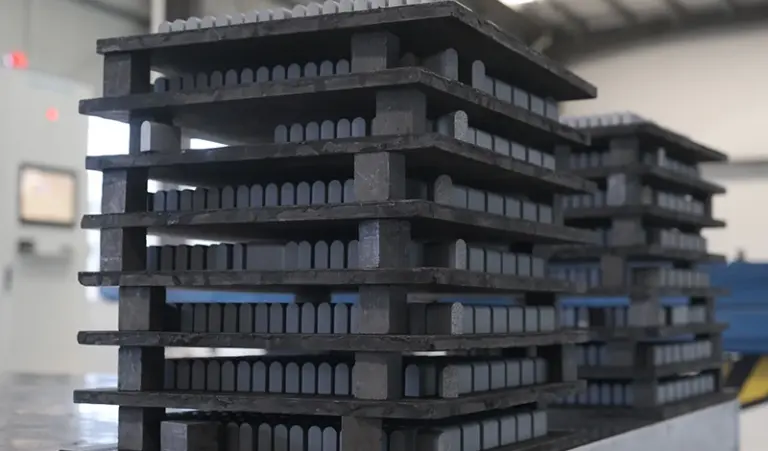
For the carbide variant, confirm the insert layout against the drawing on the carbide snow plow blade page. Insert spacing affects both the wear pattern and the weld sequence, since heat should not be concentrated next to an insert.
Decide the wear allowance before the weld
The exposed depth below the mouldboard is a design choice, not a fixed number. Too little and you replace the edge early; too much and the weld line sits where the mouldboard takes the load. Most pickup plows land in a workable band, but the right value depends on surface type, down-pressure, and how the operator sets the skids.
- Measure the current exposed depth on the worn edge, if one is still fitted.
- Note how much of that depth was actually consumed before the mouldboard was touched.
- Check whether the skids or shoes were carrying the edge off the surface.
- Confirm the trip mechanism’s travel does not let the edge contact the base angle.
- Set the new exposed depth within the range shown on the product drawing.
- Record the value so the next edge is ordered against the same figure.
If one end of the old edge was consumed faster, that is a signal about alignment or operator habit rather than about edge size. The checks in one end of the edge wearing faster are worth running before you commit to a new dimension.
Match the weld land to the base material
The weld land is the flat area on the edge that sits against the mouldboard lip. Its height and thickness must suit the base material, because a thick edge welded to thin plate pulls the plate rather than fusing cleanly. Clean the land to bare metal and check for cracks or previous weld repair before fitting.
Where the base angle has been rebuilt, treat the measured thickness as nominal and verify by drilling a small test hole or by ultrasonic check if the plow is critical to a fleet. A weld-on edge hides the joint permanently, so the preparation stage carries more weight than it does with a bolted edge.
Order against the drawing, not the description
Send the measured dimensions with a sketch and the product drawing reference. The supplier should confirm the drawing against your numbers before cutting. Keep the confirmation on file with the plow’s service record.
Price and lead time come from a written quote; specifications come from the product page. Confirm the current drawing revision for the cutting edge product family before releasing a purchase order, and state the measured dimensions on the order so the drawing and the plow are reconciled in writing.
Quick summary
Size a weld-on edge from the mouldboard’s lower lip, the available mounting height, and the old hole pattern used as a positional reference. Set the exposed wear depth deliberately, prepare the weld land to the base thickness, and order against a confirmed drawing rather than a nominal blade width.
Sources checked on 2026-11-08: SENTHAI Tools product drawing references for weld-on and carbide cutting edges; general fabrication practice for welding wear plate to mouldboard steel; field measurement notes from pickup plow service records.
Three more perspectives
Workshop. The fitter cares about the weld land and heat input. A weld-on edge that measures correctly but sits on a distorted lip will crack at the toe within a season. Jig the mouldboard straight before welding, and stagger the passes so the inserts are not heat-cycled.
Purchasing. The order needs the drawing revision and the measured dimensions on the same document. Without both, a correct part can be rejected at goods-in because it does not match the description on the requisition.
Field. The operator judges the edge by how it clears and how the skids run. Record the exposed depth at fitting and again at removal; that pair of numbers is the most useful input for the next order.
Limits
This page does not give a universal dimension set, a weld procedure specification, or a wear-life guarantee. Dimensions and hole spacing follow the product page and the confirmed drawing; life and cost depend on surface, down-pressure, and operating hours. It is not a substitute for the plow manufacturer’s instructions or for a qualified welder’s judgement.