Most inserts that come off a plow edge in service did not wear out. They were released, and the release happened at the joint, where a bond that looked sound at inspection was never fully formed across the contact area.
That makes the joining step the one that decides whether the carbide ever gets the chance to wear as designed. This is what the joint has to survive, how the method affects repeatability, and what a buyer can ask to see.
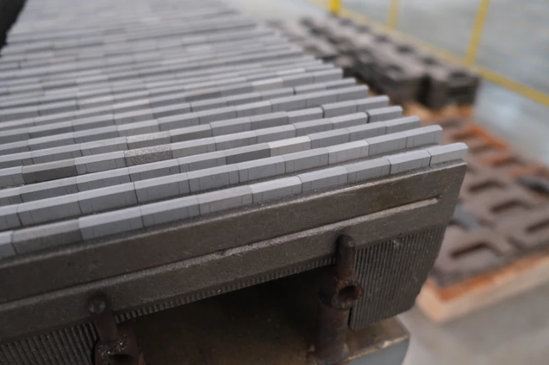
Brazing plow edges: why the joint fails first
The joint usually ends an edge’s life before the carbide.
The carbide wears at a predictable rate, while a braze that is under-bonded, contaminated or cooled too quickly releases the insert under load, which is why the joining step is where edge life is actually decided.
The reason is mechanical. Carbide is hard and brittle, so it cannot be welded without cracking; it has to be attached with a filler metal that melts below the temperature at which the carbide degrades. That filler forms the load path between the insert and the steel, and it is far weaker in shear than the carbide is in compression, so it becomes the limiting component by design.
Three conditions decide whether that limiting component performs: the surfaces have to be clean enough for the filler to wet them, the temperature has to reach the flow point evenly, and the cooling has to be controlled. Each of the three can fail invisibly, which is why the record matters as much as the process.
What the braze joint has to survive
The joint carries three different loads on a plow edge, and they do not peak at the same moment.
The first is shear, from the drag of the edge across the surface. The second is impact, when the blade meets a raised manhole cover, a frozen ridge or a curb. The third is thermal, because the edge works in sub-zero conditions and the two materials contract differently. A joint that performs well in shear can still fail in impact if the bond area is small.
The load also varies along the edge. Inserts near the ends of a plow see more impact than those in the middle on some machines, and a wing or underbody edge takes loads a front blade never sees. That is why the same insert and the same filler can behave differently on two applications, and why the joining process is specified against the application rather than against the product alone.
Filler metal selection
The filler is chosen for its flow temperature and its ability to wet both the carbide and the steel, not by preference.
Silver-based fillers are common on carbide-to-steel joints because they flow at a temperature the carbide tolerates and wet both surfaces well, which gives a consistent bond at a controlled heat input. Copper-based fillers are used where the service temperature and the cost allow, and they require more heat to flow, which is a consideration when the nearby material is sensitive to thermal history.
The selection also interacts with the body. A thicker section draws heat away from the joint, so the filler has to flow within a window that the process can actually reach on that part. Where a filler works on a thin edge and fails on a heavy one, the problem is often the heat path rather than the filler itself.
Automated induction versus torch methods
The difference between an automated induction process and a torch is repeatability rather than temperature.
A torch applies heat to one area at a time, so the result depends on where the operator directs it and for how long. An induction coil heats the joint area by design, and the cycle is set so that every piece receives the same time and temperature relationship. Both can produce a good joint; only one produces the same joint on the thousandth piece as on the first.
Repeatability is what makes inspection meaningful. Where the process is automated and recorded, an inspection result describes the process as well as the piece. Where the process varies with the operator, an inspection only describes the pieces that were inspected, which is a much weaker statement for a delivered lot.
Temperature control and repeatability
The joint forms in a narrow window, and the window is defined by the filler rather than chosen for convenience.
Below the flow temperature the filler does not wet the surfaces and no bond forms. Above the upper limit the carbide is exposed to a thermal history it tolerates poorly, and the steel may change properties as well. Within the window, the joint needs enough time for the filler to flow through the gap by capillary action, which depends on the clearance between the two surfaces.
| Control | What it determines | What drift produces |
|---|---|---|
| Joint clearance | Whether filler can flow through the gap | Incomplete bond area despite an even fillet |
| Peak temperature | Whether the filler flows without degrading the carbide | No bond if low; cracking or a damaged insert if high |
| Time at temperature | How far the filler travels across the joint face | Bond concentrated at the edges rather than through the joint |
| Surface condition | Whether the filler wets the two surfaces | Bond that appears sound and releases under load |
| Cooling rate | Residual stress in the insert and the steel | Cracks that appear after fitting rather than at inspection |
Read the table downwards and it becomes a fault-finding order. If the insert released, check clearance and surface condition first, because those produce a joint that looks correct; then check the thermal record, because that produces a joint that looked correct and then cracked.
Joint defects and detection
Joint defects fall into two groups: those that reduce the bonded area, and those that damage one of the two materials.
Reduced bond area comes from contamination, insufficient clearance, too little time at temperature, or filler that flowed away from the joint. Material damage comes from overheating, from thermal shock during cooling, or from a mismatch between the filler and the application. Both can pass a visual check, which is why visual inspection alone is a weak control.
| Defect | How it arises | Detection |
|---|---|---|
| Incomplete bond area | Contamination, wrong clearance or short time at temperature | Destructive shear or bend test on a sample; process record for the lot |
| Excess filler or voids | Clearance outside the range, or filler that flowed unevenly | Visual and dimensional check; cross-section on a sample |
| Insert cracking | Overheating or rapid cooling after the joint | Visual inspection after cooling; crack detection on suspect lots |
| Body distortion | Heat input across a thin or unrestrained section | Dimensional check against the drawing after joining |
| Corrosion at the joint | Residues left after the process, where flux was used | Visual inspection and cleaning verification |
The fourth row is the one that shows up as a fitment complaint rather than as a joint failure. A body that moved during joining can still hold its inserts perfectly and still fail to bolt onto the machine, which is why the dimensional check follows the joining step rather than preceding it.
Strength testing approaches
Strength testing on a production line is about consistency rather than about one spectacular number.
Shear testing applies a load across the joint and records the value at which it fails; bend testing loads the insert in a way that resembles an impact and shows whether the failure runs through the filler or through the carbide. Both are destructive, so they are run on samples from a lot rather than on the parts that ship.
The useful output is a trend rather than a single result. Where sample results from successive lots sit in a stable band, the process is under control; where the values move, the change is visible before a field failure makes it obvious. Test methods that a specification can reference come from bodies such as ASTM International and the American Society of Mechanical Engineers.
What to ask a supplier to document
The documentation request should be short enough to be met on every lot and specific enough to be useful.
Five items cover the joining step for a normal production lot, and each has a reason a supplier can understand.
- The joining method and the equipment class used, so a change of method is visible.
- The filler metal specification, so the joint can be compared with the drawing.
- The parameter window the cycle was run inside, without necessarily disclosing set points.
- The inspection applied after joining, and the result recorded for the lot.
- The dimensional check after joining, confirming the body is still within tolerance.
The fifth item is the one buyers forget to ask for and the one that catches distortion. A process that produces sound joints and out-of-tolerance bodies is not under control, however good the joint inspection looks. The joining process SENTHAI uses, and the routine behind the lot records, are described on the quality control page.
Why the joint, not the carbide, sets the edge life
Edge life is the shorter of two lives, and the joint is almost always the shorter one.
The carbide’s wear rate can be estimated from the grade and the surface, and it is broadly predictable. The joint’s life depends on whether it was fully bonded, which is a process outcome rather than a material property. That is why two edges with the same insert and the same steel can last very differently on the same route.
The practical conclusion for a buyer is that grade selection and joining control are not competing specifications. A harder grade on a well-formed joint improves wear; the same grade on an under-bonded joint simply loses inserts faster, because the harder material transfers more load to the joint.
Where brazing differs from welding
Brazing and welding solve different problems, and the difference explains the whole process design.
Welding melts the parent metals and produces a joint that is metallurgically continuous with them. Brazing melts only the filler, which flows between the two surfaces and bonds them without melting either. For carbide that distinction is decisive, because the temperatures welding requires would damage the insert before the joint formed.
Standards that describe these processes and the qualifications behind them come from the same bodies cited above, and the fleet-side conventions for edge and bolt patterns are published by the American Association of State Highway and Transportation Officials and SAE International. The welding and joining conventions used in manufacturing are also covered in the sector material published by the Snow and Ice Management Association.
FAQ
Why is brazing used instead of welding for carbide inserts?
Welding melts the parent metal and produces local heating that carbide cannot tolerate without cracking. Brazing joins the two with a filler that flows below the melting point of both, which keeps the carbide out of the temperature range where it fails.
What filler metal is normally used?
Silver-based fillers are common for carbide to steel because they flow at a temperature the carbide tolerates and wet both surfaces well. Copper-based fillers are also used where cost and temperature allowance permit. The choice is made against the service temperature and the load, not by preference.
Can a lost insert be repaired in the field?
It can be replaced rather than repaired, and only with the right filler and a controlled heat source. A field repair that relies on a torch and a general-purpose rod usually leaves a joint weaker than the original, and it removes the piece from any traceability the lot had.
How does a buyer tell a good joint from a poor one?
From the record rather than the appearance. A fillet that looks neat can sit over an under-bonded area, so what a buyer can use is the inspection method the supplier applied, the result recorded per lot, and whether the process is automated or manual.
If insert retention is the problem you are trying to solve, send the application and the failure pattern. SENTHAI will answer with the joining method, the parameters that matter and the record that travels with each lot.