A neat fillet around an insert is a comfortable thing to see and a poor proof of anything. The filler that forms the fillet reached the outside of the joint, and whether it filled the area carrying the load is a different question.
What a buyer can act on is the method applied, the sample it was applied to, and the result recorded. This is what each method actually proves, and how to write the requirement into an order.
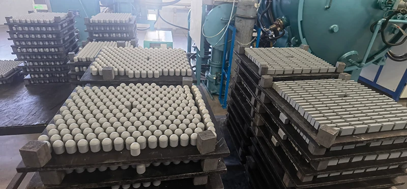
Brazed joint testing: what each method proves
Each test proves something different about a braze joint.
Visual inspection shows the fillet, dimensional checks show whether the body moved, shear and bend tests show the bonded area, and ultrasonic or radiographic methods look for what none of the others can see.
The reason one method is never enough is that the failure modes sit in different places. A contaminated surface produces a joint with a complete fillet and no bond in the middle, which only a destructive test or a volumetric method reveals. An overheated joint produces a cracked insert with a perfect fillet, which a visual check after cooling will catch. A distorted body produces no joint defect at all, only a footprint that no longer matches the machine.
Choosing the method is therefore a question of which failure the buyer is trying to rule out, and a specification that names one method is naming one answer.
Visual and dimensional inspection
Visual inspection confirms that the process ran and that the visible geometry is correct, and it is the cheapest control available.
What it can show is whether the filler flowed to the edges, whether it flowed evenly along the joint, whether there are obvious voids or gaps at the fillet, whether the insert cracked during cooling, and whether residues from the process were cleaned off. What it cannot show is the proportion of the joint face that is actually bonded.
The dimensional check belongs beside it, and it is aimed at the body rather than the joint. Heat applied during brazing can move a thin section, so measuring the footprint and the critical dimensions after joining is what confirms that the part will still fit. Doing that check before joining rather than after is one of the more common process mistakes in this stage.
Ultrasonic and radiographic options
Volumetric methods look inside the joint, which is the only way to find an unbonded area without destroying the part.
Ultrasonic inspection sends sound through the joint and reads the reflection from the interface, so it can indicate areas where the two surfaces are not bonded. It works better on flat, parallel joints than on complex geometry, and it needs a reference standard to interpret against. Radiographic methods image the joint and can reveal voids and inclusions, but they are less sensitive to a thin, unbonded interface than to a void with volume.
Both require a reference piece to compare against, which is the practical obstacle in a supplier relationship: the buyer has to accept the supplier’s reference, or both parties have to agree on a standard sample. Where the joint is critical enough to justify the cost, agreeing that reference at the start of the programme is what makes the method usable.
Shear and bend testing
Destructive tests answer the question the non-destructive methods only approach: how much load the joint carries before it fails.
A shear test loads the joint across its face and records the value at which it separates, which gives a number that can be compared between lots. A bend or impact test loads the insert in the direction it meets an obstacle in service, and it also shows where the failure runs. If the fracture follows the filler, the joint was the weak point; if it runs through the carbide, the joint held and the insert failed.
- Take the sample from production rather than preparing it separately.
- Record the failure load and the location of the failure on the joint face.
- Note whether the fracture ran through the filler or through the carbide.
- Compare against the trend from previous lots rather than against a single value.
The fourth step is where the test produces value. A single shear result says little on its own; the same test repeated across lots shows whether the process is stable, and it is the drift that predicts a field failure rather than the absolute number.
Thermal cycling tests
Thermal cycling tests the joint against the mechanism that actually causes many winter failures: repeated differential expansion between carbide and steel.
Cycling the part between cold and warm conditions and inspecting afterwards reveals joints that were sound at room temperature and develop cracks or partial separation after a few cycles. For a product that spends a season in sub-zero conditions and returns to a warm yard between events, that is a closer model of service than a single load test.
It is rarely run on every lot, because it takes time and equipment. Its proper place is in qualification: the sample that establishes the process, and any change of filler, body material or cycle afterwards. Where a supplier has changed something in the joining area, a thermal cycling result is a more meaningful re-qualification than a dimensional check.
Destructive versus non-destructive
The two categories answer different questions, and a specification usually needs one of each.
Non-destructive methods can be applied to the parts that ship, which means they can confirm every delivered piece. Destructive methods can only be applied to samples, which means they confirm the process rather than the parts. A programme that uses only visual inspection confirms nothing about the bond; one that relies only on destructive sampling accepts that the individual pieces are unverified.
| Route | Applies to | What it confirms | Main limitation |
|---|---|---|---|
| Visual and dimensional | Every piece | Filler flow, visible defects, footprint | Says nothing about the bonded area |
| Ultrasonic | Every piece, where geometry allows | Unbonded areas inside the joint | Needs a reference standard and suitable geometry |
| Radiographic | Sampled or critical pieces | Voids and inclusions with volume | Less sensitive to a thin unbonded interface |
| Shear and bend | Samples | Load capacity and failure location | Destroys the sample; confirms the process, not the piece |
| Thermal cycling | Samples at qualification | Durability under differential expansion | Slow; unsuitable as a routine lot control |
Read as a set, the table describes an inspection plan rather than a test. Every-piece methods cover what can be seen; sampling methods cover what cannot; and qualification methods cover the durability question that neither covers in routine production.
Sampling plans that mean something
A sampling plan means something when it is tied to the failure it is meant to catch, rather than to a convenient quantity.
Three elements make a plan usable. The sample has to come from the production run rather than from pieces made specially for the test. The sample size has to be related to the lot and to the risk, so that a small lot is not tested at a rate that makes the test meaningless. And the plan has to state what happens when a sample fails, which is normally containment of the lot rather than a note in the file.
The third element is what distinguishes a control from a ceremony. A test whose failure triggers no action is a record of an outcome, and it tells the buyer nothing about the parts that shipped alongside the sample.
Interpreting test reports
A test report can be read in a minute if the buyer knows what to look for, and there are four items worth checking first.
The report should identify the sample by batch reference, state the method and the standard it was performed to, give the measured values rather than a verdict, and name the equipment or laboratory that performed it. A report that gives a pass verdict without values cannot be compared with the next lot, and one that does not name the sample cannot be tied to the goods.
- The batch reference, so the result can be tied to the delivered parts.
- The method and standard, so the result can be reproduced or challenged.
- The measured values, so successive lots can be compared rather than judged.
- The testing party, so the result can be weighted accordingly.
Test methods and standard practice for these measurements come from bodies such as ASTM International and the American Society of Mechanical Engineers, with measurement practice published by the National Institute of Standards and Technology.
Writing the test into the order
A test that is not written into the order is a test the supplier may stop performing when the order pressure rises.
The clause does not need to be long. It needs to name the method, the sample basis, the acceptance approach and the record that will be supplied. Where a qualification test is required, the clause should also say when it has to be repeated, which is normally on any change to the filler, the body material or the joining cycle.
- Name the method and the standard it is performed to.
- State whether the test applies to every piece, to samples from each lot, or to qualification only.
- State the acceptance approach: a limit, a band, or a trend reviewed over successive lots.
- Name the record that will be supplied with the lot, and the batch reference it will carry.
- State the trigger for repeating a qualification test after a process change.
The third item is where buyers most often over-specify, and it is worth resisting. A simple pass limit invites a supplier to make the sample pass rather than to control the process, while a trend reviewed across lots reveals the drift that matters. Equipment and fitment conventions that the specification may also reference come from SAE International and the American Association of State Highway and Transportation Officials, and the sector’s documentation practice is published by the Snow and Ice Management Association.
FAQ
Is a neat fillet enough to prove a sound joint?
No. A fillet is formed by filler metal that has flowed to the edge of the joint, and it can be complete on a joint that is only partly bonded in the middle. The fillet shows that the filler flowed at all, not that it filled the area carrying the load.
Does brazing require a certified operator?
It depends on the standard the product is made to. Where a specification names a brazing standard, the process usually requires qualified procedures and, for manual work, qualified personnel. On automated equipment the qualification attaches to the procedure and the equipment rather than to an operator.
What joint clearance should be specified?
Enough for the filler to flow by capillary action and no more. The usable range is set by the filler and the joint geometry, and it is normally stated as a range rather than a value. A clearance outside that range produces voids if it is too wide and starves the joint if it is too tight.
If joint quality has to be provable rather than visible, tell SENTHAI which failure you are trying to rule out. The reply will name a method, a sample basis and the record that comes with each lot.