A bolt pattern can be within tolerance on the drawing and still be two millimetres out of position on the machine, because the tolerance that matters is not the one on each hole but the one on the pattern as a whole.
Tolerance control is the discipline of deciding which dimensions carry that consequence and then measuring them the same way every time. This is how a measurement plan is built, and where it usually fails.
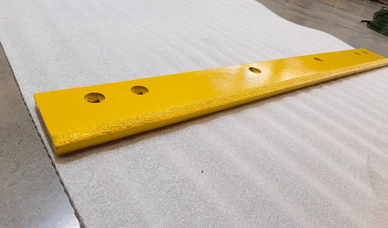
Dimensional inspection plow edges: what has to be held
Four dimensions decide whether a plow edge works.
The bolt pattern as a layout, the mounting face it sits on, the overall length and the edge thickness; the first two decide fitment and the last two decide wear and seating.
Everything else on the drawing matters for appearance or for a secondary interface, and treating it with the same tolerance as the four above raises the cost without improving the product. That is the argument for a measurement plan: it is a decision about where the tolerance budget is spent, not a list of every dimension on the drawing.
The plan also has to say how each dimension is measured. A pattern checked with a tape and a pattern checked on a fixture are two different measurements, and a record that does not state which was used cannot be compared between lots.
Critical dimensions to control
Critical dimensions are the ones where a deviation reaches the customer, and they are usually fewer than the drawing suggests.
The bolt pattern is critical because position error accumulates with the plate it bolts to, and because the holes are the interface the fitter cannot adjust. The mounting face is critical because a face that is not flat loads the edge unevenly. The overall length is critical where edges are run in sequence on a moldboard, since a length error changes the lap between segments. The edge thickness is critical because it sets the wear volume and the seating angle.
Two further dimensions deserve to be named as critical on carbide edges: the insert exposure above the body, and the position of the first and last insert relative to the ends. Both affect wear behaviour and neither is caught by an overall length check.
Measuring instruments, gauges and fixtures
The instrument has to match the tolerance, and the match is a matter of resolution rather than of cost.
A general rule is that the measuring equipment should resolve to about a tenth of the tolerance it is checking. Where the tolerance is tight, that points to a coordinate measuring machine or a dedicated gauge; where it is loose, a rule and a go or no-go gauge are adequate and much faster.
| Dimension | Typical method | Why this method |
|---|---|---|
| Bolt pattern as a layout | Fixture with pins, or coordinate measurement | Position must be checked as a set, not hole by hole |
| Mounting face flatness | Surface plate with a dial indicator, or a straight edge and feeler | Detects the bow that loads the edge unevenly |
| Overall length | Tape or calliper against a reference block | Cheap, fast and adequate for a loose tolerance |
| Edge thickness | Micrometer at named positions | Thickness varies along the edge and matters at wear points |
| Insert exposure | Depth gauge or dedicated gauge | Small tolerance with a direct effect on wear |
The third row is the one buyers argue about, because a tape measure looks crude next to a coordinate machine. It is the right instrument where the tolerance is loose; using a slower method adds cost without adding information, and a measurement plan that over-specifies tends to be the first one abandoned under production pressure.
A fixture is what turns a measurement into a repeatable one, because it fixes the datum the values are taken from.
Without a fixture, two inspectors measure the same part from two different reference points and produce two results that do not agree. With one, the part is located the same way every time, and the values can be compared across a shift, a lot and a season.
Fixture design follows the drawing datums. The locating points should correspond to the surfaces the part is measured from, and the clamping should not distort the part while it is being measured. That last point is a common source of apparent non-conformance: a part clamped hard on a fixture can read inside tolerance and be outside it when it is unloaded.
Tolerance stack against the moldboard
The tolerance stack is what connects the drawing to the machine, and it is the step most often skipped.
An edge bolts to a mounting plate, which is attached to a moldboard, which is positioned by the machine. Each element carries its own tolerance, and they accumulate: the position of a hole in the edge, the position of the corresponding hole in the plate, and the plate’s own mounting allowance. The stack decides whether the worst-case combination still fits.
Where the stack shows a problem, the fix is usually to tighten the element with the largest contribution rather than to tighten everything. That is a specification decision rather than a production one, and it is much cheaper to take before tooling is made than after a season of fitment complaints.
Sampling and capability studies
Sampling tells the supplier whether the process is holding the dimension, and a capability study tells them whether it can.
Sampling on a running lot detects drift: a first piece, a middle piece and a last piece from a run, measured and recorded, will show a trend before the values leave tolerance. A capability study compares the spread of the process against the tolerance band and shows whether the process is comfortable or marginal, which is a different question.
A process that is marginal will fail periodically no matter how closely it is inspected, because inspection finds the failure rather than preventing it. That is why the study belongs in the setup of a new part or a new tool rather than in routine production.
Records and certificates
A dimensional record is useful when it shows values against a named revision, and weak when it reports a verdict.
The record should name the drawing revision, list the dimensions measured, give the values rather than a pass mark, state the instrument used, and carry the batch reference. With those five items, two lots can be compared and a drift can be seen; without them, the record confirms that somebody looked.
The revision is the item buyers most often leave out of the requirement, and it is the one that resolves the most disputes. Where a drawing has changed, a lot measured against the old revision is not a defective lot; it is a lot made to a superseded specification, and the record is what shows which of the two happened.
Corrective action triggers
Corrective action works when the trigger is defined before the result arrives.
The trigger can be a value outside the band, a trend within the band across three consecutive checks, or a customer complaint that points back at a dimension. Each should have a stated response, and the response should include looking backwards to identify how much material was produced under the same condition.
- Hold the lot and quarantine the pieces made since the last conforming check.
- Identify the stage that produced the deviation, whether tooling, fixture or process.
- Correct the cause and re-measure before production restarts.
- Record the correction against the batch, with the date and the person responsible.
- Review whether earlier lots from the same tooling are affected.
The fifth step is what distinguishes a corrective action from a repair. A tooling problem that has been present for a week has produced more than the lot in which it was discovered, and finding the beginning is what limits the exposure.
Setting up a measurement plan
A measurement plan can be built in an afternoon, and it prevents most of the disputes that follow a fitment complaint.
The plan states what is measured, how, how often, and what happens to the result. It should fit on one page, because a plan that nobody reads is a plan that nobody follows.
- List the dimensions from the drawing and mark the four or five that are critical to fitment and wear.
- For each critical dimension, name the instrument and the datum it is measured from.
- Agree the fixture that locates the part, and record it as part of the method.
- Set the sampling: first, middle and last of each run, plus a check after any tooling change.
- Define the record format, including the drawing revision and the batch reference.
- Define the response to an out-of-band result, and who decides.
Dimensioning and tolerancing conventions for the drawing itself come from standards published by the American Society of Mechanical Engineers and the measurement practice published by the National Institute of Standards and Technology. Where the pattern has to match fleet equipment, the references come from the American Association of State Highway and Transportation Officials and SAE International.
What a buyer can verify at goods-in
Goods-in verification is not a repeat of the supplier’s inspection, and it does not need to be.
Three checks cover most of the risk: the drawing revision on the record against the revision in force, the batch reference on the record against the mark on the parts, and a trial fit or a gauge check on one piece from the lot. The first two are documentary and take a minute; the third is the only physical check most buyers need.
Where a buyer wants more, a coordinate measurement on a single piece from a new supplier or a new tooling setup is worth more than routine measuring of every delivery, because the setup is where a systematic offset would appear.
Where tolerance control fails
Four failures account for most dimensional problems, and none of them is a measuring problem.
The first is a general tolerance block applied to every dimension, which leaves the critical ones under-controlled. The second is a pattern checked hole by hole rather than as a layout, which cannot detect a systematic position shift. The third is a datum that is not stated, so two measurements of the same part disagree. The fourth is a record that carries a verdict instead of values, which makes lot-to-lot comparison impossible.
All four are specification and method problems rather than production problems, and all four are fixed before the first order rather than after a complaint. Test and measurement standards that a specification can reference are published by ASTM International, and the buying practice behind fleet specifications is documented by the Snow and Ice Management Association. The inspection routine SENTHAI applies to a lot is described on the quality control page.

FAQ
Which dimensions matter most on a plow edge?
The bolt pattern as a layout, the mounting face, the overall length and the edge thickness. The first two decide whether the edge fits at all; the last two decide how it wears and how it sits against the moldboard.
Is a general tolerance block on the drawing enough?
It is convenient and it is not sufficient. A general block spreads the same allowance across every dimension, which is expensive to hold and hides which dimensions actually affect fitment. Marking the critical ones concentrates the attention where it belongs.
How many pieces should be measured per lot?
Enough to show the spread, not enough to become a production bottleneck. Measuring a first, middle and last piece from a run, and recording the values rather than a pass mark, usually reveals a drift earlier than a larger sample measured once.
What should happen when a dimension drifts?
The lot is held, the cause is identified at the stage that produced it, and the pieces made since the last good check are reviewed. A drift that is noticed but not traced back leaves a window of suspect material in the system.
Send the drawing and the machine the edge fits, and SENTHAI will return a measurement plan naming the critical dimensions, the method and the record that travels with each lot.