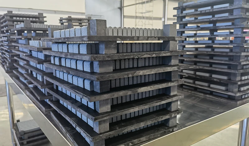
For high-impact wear parts: material strategies for shock loading, the best result comes from matching the component, material, and setup to a documented operating condition, then validating fit, wear, safety, and cost in a controlled trial. This updated guide uses current search evidence and official-source checks to turn the topic into a repeatable selection process.
Updated: October 19, 2026
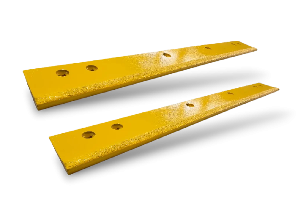
Two wear plates on the same machine can fail in opposite ways. One thins gradually across the working face and is replaced when it reaches a wear limit; the other looks almost new until a corner breaks off and takes the fixing with it.
Both plates met a specification, and one of them met the wrong one. The difference between them is whether the load arriving at the surface is abrasion or impact, and that question is settled at the position rather than at the plant.
High impact wear parts: the first question is whether impact dominates
The first question is whether impact or abrasion dominates.
A part chosen for abrasion resistance fails by cracking where the load arrives as a blow, and a part chosen for toughness wears away quickly where the load arrives as sliding contact. Identifying which load dominates at each position is the decision that determines everything else in the specification.
The identification is made from the failure, not from the drawing. Thinning across a face, with the loss distributed evenly and the edges still square, is abrasion. Cracking, spalling, deformed edges and material missing in pieces are impact. A position that shows both has a mixed duty, and the answer there is a composite rather than a compromise: a hard phase to resist the abrasion, carried in a matrix or on a base that can absorb the blow.
Getting this wrong is expensive in a specific way. An impact position specified for abrasion fails suddenly and often damages the structure the part was protecting, so the replacement cost is a fraction of the actual cost.
Hardness and toughness balance
Hardness and toughness move in opposite directions in a given material, and the specification is a position on that line.
Hardness resists the penetration and cutting that abrasion produces, so a harder surface loses less volume per unit of sliding distance. Toughness resists crack initiation and propagation, so a tougher material absorbs a blow by deforming rather than fracturing. The two properties are controlled by the same things, which is why a material cannot be maximised on both in the same volume: increasing the hard phase or the carbon content raises hardness and lowers the energy the material can absorb before it cracks.
The practical way to think about the trade is through energy. An impact delivers energy in a short time, and the material has to dissipate it. A hard, brittle surface can only dissipate it by cracking; a tougher material deforms and spreads the load. Where the energy per event is high, the second behaviour wins even though the surface is softer and wears faster under sliding.
Test methods for the mechanical properties behind this decision come from ASTM International and, for pressure equipment and structural applications, from ASME. Material verification practice is described by the National Institute of Standards and Technology.
Composite and insert strategies
Compromise is avoided by separating the functions, and composites are the standard answer for mixed duty.
The common strategies are these. A hardfacing or overlay applied to a tough base keeps the bulk material ductile while giving the surface abrasion resistance, and it can be renewed in place. Carbide inserts brazed or mechanically fixed into a steel body put a very hard phase exactly where the wear occurs, with the base carrying the structural load. Composite castings, where hard particles are distributed through a tougher matrix, give a uniform wear surface that tolerates moderate impact. And ceramic or carbide tiles bonded to a structure create a wear surface that is replaced rather than rebuilt.
Each strategy has a limit set by the bond rather than by the hard phase. An insert that is correctly specified and badly bonded will be lost as a whole piece, and the failure will look like an impact failure when it is really a process failure. Bonding quality is therefore part of the material strategy rather than a downstream manufacturing detail.
Failure modes under shock
Shock failures divide into a small number of recognisable modes, and each one points at a different correction.
Chipping removes a piece from the edge or corner where the load is concentrated, which usually indicates a hard phase that is too coarse or a surface that is too hard for the energy arriving. Spalling lifts a plate from the surface, which points at a bond or substrate problem rather than at the wear material. Cracking through the body indicates that the section is too thin for the load or that the base material lacks toughness. Deformation without fracture indicates a material that is too soft for the abrasion the position also sees, and that position needs the composite treatment rather than a harder alloy.
The distinction between chipping and spalling is worth making carefully, because the first is a material selection problem and the second is often a manufacturing one. A workshop that treats them as the same failure will change the grade when the process was the cause.
Testing approaches
Testing has two parts: verifying the material and reproducing the duty, and the order matters.
Work through the sequence below when a new wear part is being qualified.
- Verify the material and its mechanical properties against the specification, with the method stated.
- Confirm the bond or fixing on a sample, because a composite fails at the interface before the hard phase fails.
- Measure the dimensions that decide fit and the ones that decide the wear volume available.
- Run a service trial at the actual position, with the feedstock and speed recorded.
- Compare the trial against the incumbent part on the same position and the same material stream.
A trial that changes both the position and the material proves nothing. The comparison has to hold one constant, which is why a service trial takes longer to arrange than a bench test and answers the question the bench cannot.
Selection matrix
The matrix below sets out which material strategy suits which dominant load.
| Dominant load | Strategy | What it trades away |
|---|---|---|
| Sliding abrasion, low impact | Hard carbide or a high-hardness overlay | Tolerance of shock; risk of chipping at edges |
| Moderate impact with abrasion | Composite with a tough matrix and a hard phase | Peak hardness, and therefore the lowest possible wear rate |
| High impact, low abrasion | Tough alloy steel, work-hardening grades where available | Wear resistance under sliding contact |
| Mixed duty, reversible position | Bolt-on carbide or ceramic elements on a structural base | Higher part cost and a fixing that has to be maintained |
The matrix is a starting point for the enquiry, and the answer is confirmed by the service trial rather than by the table.
Supplier documentation
Documentation is what makes a wear part specification repeatable, and it should be requested in the enquiry rather than after the first failure.
- The material or grade specification, with the properties that were verified and the method used.
- The bonding or fixing method and the inspection applied to it.
- The dimensions inspected on each lot and the tolerance applied to them.
- The lot identification, so that a field failure can be traced to its production batch.
Equipment categories and machine-level context for the equipment these parts are fitted to are described by the Association of Equipment Manufacturers, and material industry context by the International Tungsten Industry Association.
Where a softer material outlives a harder one
There are three situations where the softer part lasts longer, and all three are common in heavy equipment.
The first is any position where the load arrives as a blow, because the harder part fractures and the tougher material deforms and carries on. The second is a position where the fixing is the weak point, since a hard and brittle part can transmit shock into the bolts and take the mounting with it. The third is a position where a hard surface chips into a downstream process, and the cost of the contamination exceeds the cost of the wear part.
In all three, the harder material has not failed as a material; it has failed as a system choice. That is why the recommendation is to identify the dominant load first and to treat hardness as one property among several rather than as a quality ranking.
Specifying for a mixed duty
A mixed-duty position needs the two functions separated in the specification, which usually means a composite and a defined replacement interval.
| Item | Why it belongs in the specification |
|---|---|
| Dominant load, with the evidence | It selects the strategy and prevents a grade change later |
| Hard phase and matrix or base | Both decide the result, and only one of them is usually quoted |
| Bond or fixing method | Most composite failures begin at the interface |
| Wear volume available | It sets the replacement interval, which is the cost driver |
| Replacement trigger | Converts an unplanned failure into scheduled work |
SENTHAI produces carbide wear parts on an in-house process chain that includes pressing, vacuum and low-pressure sintering, and automated high-temperature induction brazing, which is the step that determines how well a hard phase stays attached to its base. The carbide insert range shows the grades and tolerances available, and the process behind them is described on the factory page.
Match the Edge or Attachment to the Actual Operating Condition
This research-backed framework closes a recurring gap in pages ranking for High-Impact Wear Parts: Material Strategies for Shock Loading: readers need a decision method, not a list of unsupported superlatives. Apply the same evidence fields to every option before choosing high-impact wear parts: material strategies for shock loading.
| Decision gate | Evidence to collect | Release rule |
|---|---|---|
| Surface | Asphalt, concrete, gravel, pavers, bridge deck, or sensitive finish | Choose material and setup that protect the surface while meeting removal goals |
| Snow and ice | Loose snow, wet snow, compacted snow, bonded ice, or mixed conditions | Separate plowing, scraping, and deicing functions |
| Machine setup | Carrier weight, attack angle, down pressure, shoes, trip system, and speed | Verify the complete system rather than judging the edge alone |
| Validation | Short route trial, photographs, wear readings, fuel or time, and operator notes | Expand only after the trial meets a written acceptance rule |
The most useful choice is the one that meets the route objective without shifting damage or downtime elsewhere in the system. Record setup and operating conditions so the result can be repeated.
Run a Controlled Trial Before Full-Fleet Adoption
-
Freeze the baseline: record the current component, carrier settings, route, weather, operator, hours, and reason for removal.
-
Approve fit first: compare the supplier drawing with the machine and attachment. Do not drill, grind, weld, or substitute fasteners without an approved procedure.
-
Change one major variable: keep route and operating method as consistent as practical so the result can be attributed to the component rather than a different setup.
-
Inspect at planned intervals: photograph the same locations, measure wear, check fastener torque and retention, and log impacts or abnormal vibration.
-
Release against written criteria: decide in advance what wear, removal quality, downtime, and cost per operating hour would justify expansion.
Official-Source and SERP Verification
The technical boundary was checked against Federal Highway Administration snow and ice guidance. That source is used for the operating or safety context; model-specific dimensions, settings, and limits must still come from the approved manual for the exact machine and component. The following leading pages were reviewed for search intent and missing decision details:
Frequently Asked Questions
What should be verified before selecting high-impact wear parts: material strategies for shock loading?
Confirm the exact application, dimensions, carrier limits, operating surface, expected impacts, supplier drawing, and acceptance evidence. A product name or grade label alone is not enough.
How should high-impact wear parts: material strategies for shock loading be compared on cost?
Compare landed and installed cost, service hours, maintenance labor, downtime, collateral wear, and replacement reason. Use cost per operating hour for comparable routes rather than purchase price alone.
When is a trial required?
Use a controlled trial whenever fit, material, setup, route conditions, or supplier process changes. Define the baseline and pass criteria before the trial starts.
Which document controls installation and operating limits?
The current manual, approved drawing, and written instructions for the exact carrier and component control. General articles and cross-reference tables are screening tools, not installation authority.
Request an Application Review
Send SENTHAI the carrier or machine model, drawing or dimensions, operating surface, route condition, current failure mode, expected quantity, and target service interval. The engineering team can then review a suitable product path without changing the evidence requirements described above.