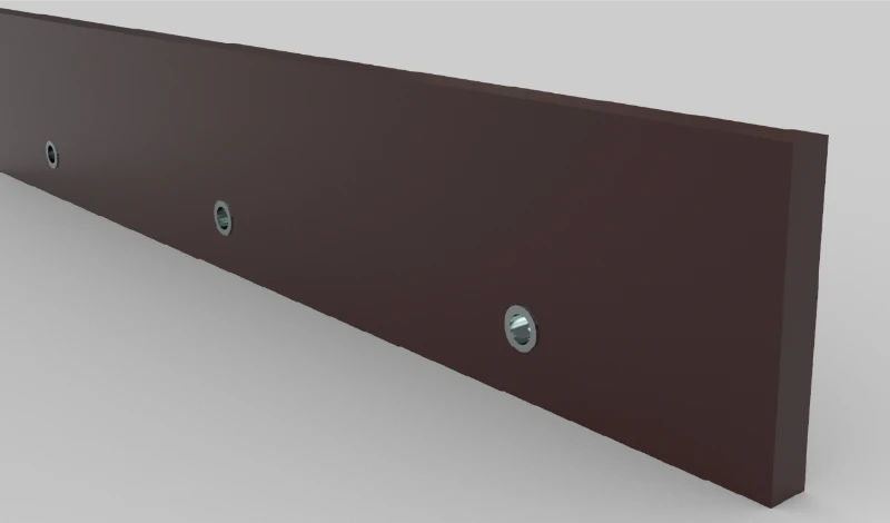
For joma articulating blades and cutting edges: how the mechanism changes wear, the best result comes from matching the component, material, and setup to a documented operating condition, then validating fit, wear, safety, and cost in a controlled trial. This updated guide uses current search evidence and official-source checks to turn the topic into a repeatable selection process.
Updated: October 19, 2026
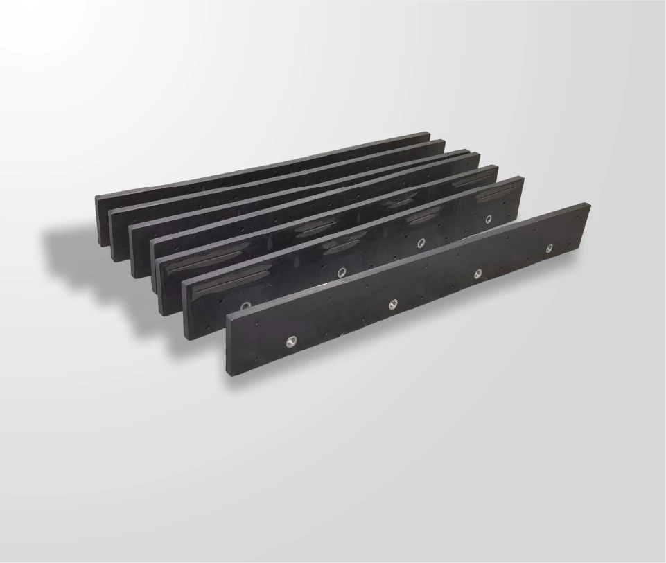
Articulation is usually sold as a way to make an edge last longer, and that is not quite what it does. It does not remove wear; it moves it. The cutting line stays in contact across a surface that changes height, so abrasion is shared over more material — and in exchange, a set of moving parts begins to wear on a schedule of their own, which is the part of the comparison most specifications leave out.
This comparison sets the articulating assembly against a fixed edge on the variables that actually separate them: where the contact goes, how the load travels through the mechanism, what wears first, and what each option costs to keep running.
What articulation solves on uneven roads
It solves the contact problem, not the wear problem.
On a crowned or patched road a fixed edge touches only the high points, so the material it touches carries the entire load while the rest of the edge does nothing.
An articulating assembly changes that geometry. Because the cutting line can move relative to the moldboard, more of it reaches the surface at any moment, and the abrasion that a fixed edge concentrates at a few points is shared across the length. On a road with repeated changes in camber the difference is immediately visible in the wear pattern: a fixed edge shows localised consumption at the high points, while an articulating one shows relatively even wear with the damage appearing where the route presents obstacles instead.
Set against a fixed edge, the trade is therefore about where the wear lands rather than whether it happens. What the articulating assembly buys is even consumption across a blade that has to work a variable surface; what it gives up is simplicity.
How the mechanism compares with a fixed edge on the same route
On a route that is genuinely uneven, the two assemblies separate on contact time. A fixed edge is in contact for a fraction of the pass, because it bridges dips rather than following them; an articulating edge stays in contact for longer, which raises the proportion of the blade doing useful work and lowers the load per contact point.
On a route that is smooth, the same comparison reverses in value without changing in mechanism. There is nothing for the articulation to conform to, so the assembly behaves as a heavier, more complex fixed edge — and the moving parts still wear. That is the case where the mechanism is being paid for and not used, and it is the reason articulating edges belong on identified routes rather than across a fleet.
Mechanical load paths in the assembly
Load arrives at the articulating edge the same way as at a fixed one and then takes a different route through the machine. Forward force is received at the cutting line, transmitted through the segment and its fixings into the moving section, and from there into the moldboard and the carrier.
The difference from a fixed edge is the extra interface. Every load now passes through a joint that is designed to move, and that joint has to transmit force in one direction while permitting displacement in another. Two consequences follow for the specification. The fixings at the articulation zone carry a load that has no equivalent on a fixed edge, and the moldboard has to tolerate a load pattern that changes as the assembly articulates rather than a steady one. Both are checkable at fitting: a mounting line that stays straight over a season is tolerating it, and one that shows distortion is not.
Wear distribution across the articulation zone
The articulation zone wears differently from the rest of the assembly, and comparing it with a fixed edge explains why fleets are sometimes surprised by the repair bill. On a fixed edge the cutting line consumes first and the structure behind it lasts; on an articulating assembly the cutting segments can be sound while the mechanism that carries them is already worn.
Three patterns appear in that zone, and each has a cause worth identifying before parts are ordered. Movement at the fixings with sound segments indicates the assembly is being loaded harder than its design expects, usually through down-pressure. Polished mating faces with no visible damage indicate normal articulation. And a section that no longer returns to its rest position after a pass indicates the moving part has taken a set, which is a replacement decision rather than an adjustment.
Points that need inspection each season
The inspection list for an articulating assembly is longer than for a fixed edge, and it follows the load path rather than the cutting line. Working through it in the order below takes the same time as a fixed-edge check and catches the failures that appear between seasons.
- Check the segment fixings at the articulation zone first, before looking at the segments themselves.
- Check the travel of the moving section through its full range by hand, feeling for binding or a position it does not return from.
- Check the mating faces for fretting polish, which indicates the joint is articulating as designed.
- Check the moldboard behind the assembly for distortion, which indicates the mounting is not tolerating the load.
- Check the segments last, measuring at marked positions as for any other edge.
Doing the checks in that order matters because a mechanism fault changes how the segments wear. Measuring the segments first and finding them worn evenly can hide a joint that has stopped articulating, which is the failure that will shorten the next set’s life as well.
Failure modes and warning signs
Four failures account for most articulating assembly problems, and each announces itself before it becomes a roadside job.
- Binding in the articulation: the assembly stops moving, and the wear pattern suddenly becomes localised as it behaves like a fixed edge.
- Loosening at the zone fixings: usually felt as a new noise or a vibration that appears at speed.
- Set in the moving section: the edge no longer returns to rest, so it cuts deeper on one side of the blade than the other.
- Moldboard distortion behind the assembly: the mounting line bows, and every subsequent edge fitted to it inherits the problem.
Classifying a failure into one of those four categories before ordering parts is what prevents the common outcome of replacing segments when the mechanism was the fault. The wear-pattern classification used for insert edges applies directly here and is set out in reading carbide insert wear patterns.
Repair versus replace decisions
The repair decision on an articulating assembly turns on which of the two systems has failed, because the cost of the parts is not the deciding factor. Sound segments with a worn mechanism, or a sound mechanism with worn segments, are both straightforward repair cases. Both worn at once usually means the assembly has been run past the point where the mechanism was protecting the segments.
The third case is the one worth judging carefully: a mechanism that has taken a set but still articulates. Replacing it restores the wear pattern the design was bought for; leaving it converts the assembly into an expensive fixed edge, which is the outcome most likely to be recorded in the records as “the flex edge did not last”. The measurement that decides it is the travel of the moving section, not the appearance of the fixings.
Compatibility with common moldboards
Compatibility is a mounting question rather than a blade question. An articulating assembly introduces movement that a fixed edge does not, so the carrier has to tolerate the load pattern that results and provide the clearance the moving section needs through the lift range.
Three checks establish it: the mounting pattern of the assembly against the measured hole pattern of the moldboard, the clearance between the moving section and the moldboard at both ends of the lift range, and the trip mechanism’s behaviour with the assembly fitted. A machine that passes all three can run the assembly without modification; one that fails on clearance is usually better served by a flexible base without articulation, which achieves surface conformity without adding a mechanism. Fitting practice for the segment assemblies is covered in installing JOMA style segments.
What the assembly costs to keep running over a season
The comparison between an articulating assembly and a fixed edge closes on maintenance rather than on purchase price. Four lines belong in it, and only the first is a parts cost.
| Line | Articulating assembly | Fixed edge |
|---|---|---|
| Consumable parts | Segments, plus mechanism parts on their own interval | Inserts or the whole edge |
| Inspection time | Longer: mechanism, zone fixings and segments | Shorter: the cutting line and its fixings |
| Mounting risk | Lower load into the moldboard | Higher load, higher distortion risk |
| Route fit | Pays on uneven surfaces | Pays on smooth surfaces and bonded layers |
Read down the last row, the conclusion is a route decision rather than a preference. An articulating assembly on a route that presents real changes in height can be cheaper to run even with its longer inspection list; the same assembly on a smooth route costs more than a fixed edge in parts and time for no change in outcome. Equipment practice for these assemblies is published by the Association of Equipment Manufacturers, and road maintenance guidance by the Federal Highway Administration.
Winter maintenance research on equipment behaviour is published by the Transportation Research Board, operator guidance by the Snow and Ice Management Association, component and mounting practice by AASHTO, and material test methods by ASTM International.
SENTHAI manufactures JOMA style articulating and rubber-flex blades with carbide wear segments in Rayong, Thailand, and confirms the mounting pattern and clearance against the customer’s moldboard before production. The range is listed on the snow plow blade hub.
Match the Edge or Attachment to the Actual Operating Condition
This research-backed framework closes a recurring gap in pages ranking for JOMA plow blade: readers need a decision method, not a list of unsupported superlatives. Apply the same evidence fields to every option before choosing joma articulating blades and cutting edges: how the mechanism changes wear.
| Decision gate | Evidence to collect | Release rule |
|---|---|---|
| Surface | Asphalt, concrete, gravel, pavers, bridge deck, or sensitive finish | Choose material and setup that protect the surface while meeting removal goals |
| Snow and ice | Loose snow, wet snow, compacted snow, bonded ice, or mixed conditions | Separate plowing, scraping, and deicing functions |
| Machine setup | Carrier weight, attack angle, down pressure, shoes, trip system, and speed | Verify the complete system rather than judging the edge alone |
| Validation | Short route trial, photographs, wear readings, fuel or time, and operator notes | Expand only after the trial meets a written acceptance rule |
The most useful choice is the one that meets the route objective without shifting damage or downtime elsewhere in the system. Record setup and operating conditions so the result can be repeated.
Run a Controlled Trial Before Full-Fleet Adoption
-
Freeze the baseline: record the current component, carrier settings, route, weather, operator, hours, and reason for removal.
-
Approve fit first: compare the supplier drawing with the machine and attachment. Do not drill, grind, weld, or substitute fasteners without an approved procedure.
-
Change one major variable: keep route and operating method as consistent as practical so the result can be attributed to the component rather than a different setup.
-
Inspect at planned intervals: photograph the same locations, measure wear, check fastener torque and retention, and log impacts or abnormal vibration.
-
Release against written criteria: decide in advance what wear, removal quality, downtime, and cost per operating hour would justify expansion.
Official-Source and SERP Verification
The technical boundary was checked against Federal Highway Administration snow and ice guidance. That source is used for the operating or safety context; model-specific dimensions, settings, and limits must still come from the approved manual for the exact machine and component. The following leading pages were reviewed for search intent and missing decision details:
Frequently Asked Questions
What should be verified before selecting joma articulating blades and cutting edges: how the mechanism changes wear?
Confirm the exact application, dimensions, carrier limits, operating surface, expected impacts, supplier drawing, and acceptance evidence. A product name or grade label alone is not enough.
How should joma articulating blades and cutting edges: how the mechanism changes wear be compared on cost?
Compare landed and installed cost, service hours, maintenance labor, downtime, collateral wear, and replacement reason. Use cost per operating hour for comparable routes rather than purchase price alone.
When is a trial required?
Use a controlled trial whenever fit, material, setup, route conditions, or supplier process changes. Define the baseline and pass criteria before the trial starts.
Which document controls installation and operating limits?
The current manual, approved drawing, and written instructions for the exact carrier and component control. General articles and cross-reference tables are screening tools, not installation authority.
Request an Application Review
Send SENTHAI the carrier or machine model, drawing or dimensions, operating surface, route condition, current failure mode, expected quantity, and target service interval. The engineering team can then review a suitable product path without changing the evidence requirements described above.