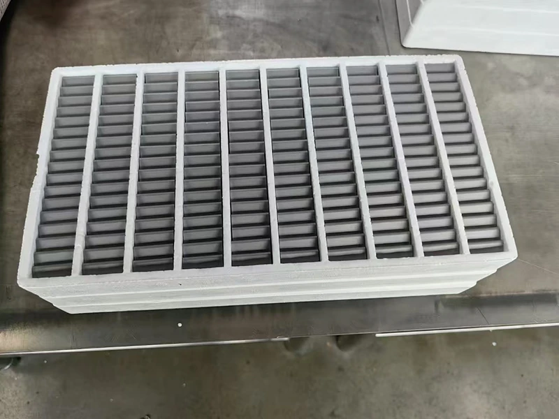
For plow blade failure modes: what each one tells you about your operation, the best result comes from matching the component, material, and setup to a documented operating condition, then validating fit, wear, safety, and cost in a controlled trial. This updated guide uses current search evidence and official-source checks to turn the topic into a repeatable selection process.
Updated: October 19, 2026
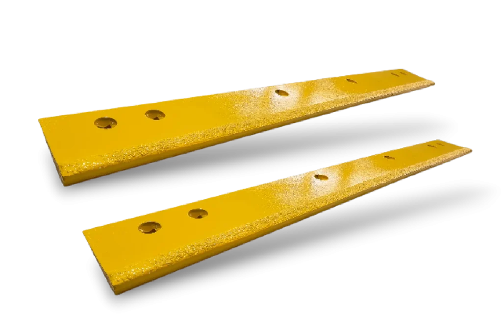
A blade comes back from a route with a scalloped edge, two cracked bolt holes and one insert missing, and the workshop replaces it. Three months later the replacement comes back with the same three conditions. Nothing in the blade specification changed, and nothing in the machine was examined, because the failure was read as a blade problem rather than as evidence about the operation.
This is a diagnostic guide organised by failure mode. Each section works back from what the blade shows to the cause that produces it, and the closing sections map the modes onto routes and operators and set out what each one calls for.
Plow blade failure modes: what each one tells you
Each failure mode points at a different cause.
The five modes that account for most blade retirements are wear-through along the working edge, localised scalloping or gouging, cracking that starts at a bolt hole, insert or edge loss from a joint, and bending from impact with a structure.
Four of them are consequences of how the machine is used or set up, and only one of them — even wear-through — is the expected result of a specification doing its job.
That distinction is what makes the diagnosis worth doing. A specification that is producing even wear is a specification that matches its route; the same specification producing scalloping or cracking is producing something the fleet did not buy, and the difference is worth more than the price of the blade.
Wear-through along the full edge
Even loss of material along the whole working width is the intended outcome, and it tells a fleet two useful things. The specification suits the route, because nothing in the setup is concentrating wear at one point. And the rate is a measurable quantity that can be used to set a replacement interval rather than reacting to each blade individually.
Where wear-through appears sooner than expected but still evenly, the causes are on the demand side rather than the supply side: more work than the fleet had allowed for, a route that has become more abrasive, or a change in down pressure. The distinction matters because the responses are different — a specification change for the first and second, a machine setting for the third.
Localised scalloping and gouging
Scalloping is localised by definition, which means the cause is local too. Four sources account for most of it.
- A raised feature on the route, such as a settled utility cut, a bridge joint or a repaired section.
- A high spot on the mounting line, which loads one part of the edge harder than the rest.
- A partially replaced edge, where a new section stands proud of its neighbours and takes the load.
- A section of frame behind the edge that has been repaired or deformed and no longer supports the edge evenly.
The third entry is the one fleets produce themselves. Replacing one section of an edge leaves it standing proud, and the scallop that follows is frequently read as a material problem. Where the scallop appears at the same position on a series of blades, the cause is the machine or the route rather than the edge.
Cracking at bolt holes
A crack that starts at a fixing hole is a fatigue signature, and it begins with movement rather than with the fastener. Where a joint loses preload the edge moves, the movement transfers load into the hole rather than into the clamped faces, and the material cracks at the point of highest stress. The crack then propagates until the hole fails or the section breaks away.
Three conditions produce that movement. An elongated hole from a previous season, which no longer locates the edge. A seat or pocket that has worn, so the edge sits on a smaller area than the design intends. And a frame that has distorted, which changes the load path across the whole pattern. Replacing the hardware without correcting any of those produces the same crack at the next change-out, which is the most common way a fleet spends money twice on one failure.
Insert loss and braze failure
Loss of inserts or of an edge section is a retention failure, and the evidence left behind identifies which stage of the joint failed. Where filler metal remains bonded to the steel and the insert has gone, the joint moved before it failed or was never seated flat. Where the seat is fretted and polished but the insert is intact, the insert has been moving for some time before it was lost.
The pattern of loss matters as much as the mechanism. Losses spread across several positions on one blade point to a batch or process cause; a single loss at one position across several blades points to a fitment or impact cause at that position. Where inserts are being lost rather than worn, the retention system is the subject rather than the material, and the mechanisms are compared on the carbide inserts page.
Bending from impact with structures
Bending is the one mode that is unambiguously an event rather than a process. It shows as a bow in the mounting line, a twisted blade, or a localised distortion where the blade met something that did not move. The blade usually survives the event; what does not survive is the geometry, and a bent blade loads its replacement edge unevenly for the rest of its life.
Two consequences follow for a fleet. The impact should be recorded against the machine, because a bowed mounting line is the cause of a whole family of downstream failures. And the operator report should be kept with the blade, because the position of the bend identifies what was hit and whether it is a route feature that will be hit again. Equipment standards that constrain what these assemblies may be fitted to are maintained by SAE International.
Failure mapping to route and operator
The useful step after identifying a mode is to establish where it comes from, and the table below maps each mode to the evidence that locates it.
| Failure mode | Most likely source | Where to look |
|---|---|---|
| Even wear-through | Normal abrasion for the specification | The route record, to confirm the demand has not changed |
| Scalloping at fixed positions | Route feature, mounting high spot or proud section | The mounting line, and the route at those positions |
| Cracking from holes | Movement in the joint | Hole condition, seat condition and frame distortion |
| Insert or section loss | Joint condition or local impact | The steel the insert came from, and the batch reference |
| Bending | A specific impact event | The operator report and the position of the distortion |
Read across the third column and a pattern appears: almost every mode other than even wear points at the machine rather than the blade. That is the practical value of the mapping, because it moves the investigation away from the part that is replaced most often.
Corrective actions by failure mode
Each mode has a corrective action, and applying the wrong one is what makes a failure repeat.
- Even wear-through: adjust the replacement interval, or change the specification if the demand has genuinely risen.
- Scalloping: correct the mounting line and the seat, and stop replacing part of an edge at a time.
- Cracking at holes: restore the seat and check the frame before fitting new hardware.
- Insert loss: review the retention method and the batch, and inspect the seat of every failed position.
- Bending: correct the blade geometry or retire it, since a bent blade will keep loading the edge unevenly.
The second and fifth entries are the ones fleets most often skip, because both require work on the machine rather than a parts order. They are also the two that produce the longest list of downstream failures if they are left.
What the pattern says about the machine
Reading several blades together says more than reading one. A fleet whose blades consistently fail at the same position along the working width has a machine or route cause that individual blade inspections will not reveal. A fleet whose failures move between machines is more likely to be looking at a route or a duty effect.
The strongest signal is a change. Where a mode appears in a fleet that has not shown it before, the cause is usually a change in duty, in the route, or in the machine, and those are all easier to find at the point they happened than a season later. Keeping the mode recorded against the machine is what makes that comparison possible.
Recording failure modes for a season
A record that supports the diagnosis has four fields: the mode, observed at removal or during service; the position along the working width; the machine and route; and the event count or kilometres the blade ran. The position field is the one that transforms a list of retirements into a map of where the fleet is losing money.
Two further notes are worth capturing where they exist. The batch reference of the edge or inserts, which allows a production question to be separated from a duty question. And any impact reported by the operator during the blade’s life, which explains a deformation that would otherwise appear without a cause.
Building a corrective action list
The end product of the exercise is a short list of changes rather than a longer list of failures.
- One specification change where even wear shows the route demand has outgrown the edge.
- One machine correction where a mode keeps appearing at the same position.
- One practice change where the fleet is producing the condition itself, such as replacing part of an edge.
Three changes a season is a realistic pace, and it is enough to move a fleet’s blade cost materially over two or three winters. Attempting more than that produces a list nobody implements, and the failures keep being read one blade at a time.
Where to start
Start with the blades that have already been retired, rather than with a new inspection regime. A workshop with a scrap pile and a set of photographs can classify a season of failures in an afternoon, and the resulting distribution of modes is enough to identify which of the corrective actions applies. What the patterns mean when read in detail is covered on the wear pattern page, and how a rotation programme fits alongside is described on the rotation programme page.
SENTHAI manufactures plow edges, wear plates and carbide inserts in Rayong, Thailand, and issues each lot with the reference that ties it to its production record, which is what makes a batch question answerable. Material test methods are published by ASTM International and ISO, joint inspection and brazing practice by the American Welding Society, winter maintenance research by the Transportation Research Board, and fleet practice by the Snow and Ice Management Association. Retired blades that need their failure modes classified can be raised through the contact page.
Match the Edge or Attachment to the Actual Operating Condition
This research-backed framework closes a recurring gap in pages ranking for Plow Blade Failure Modes: What Each One Tells You About Your Operation: readers need a decision method, not a list of unsupported superlatives. Apply the same evidence fields to every option before choosing plow blade failure modes: what each one tells you about your operation.
| Decision gate | Evidence to collect | Release rule |
|---|---|---|
| Surface | Asphalt, concrete, gravel, pavers, bridge deck, or sensitive finish | Choose material and setup that protect the surface while meeting removal goals |
| Snow and ice | Loose snow, wet snow, compacted snow, bonded ice, or mixed conditions | Separate plowing, scraping, and deicing functions |
| Machine setup | Carrier weight, attack angle, down pressure, shoes, trip system, and speed | Verify the complete system rather than judging the edge alone |
| Validation | Short route trial, photographs, wear readings, fuel or time, and operator notes | Expand only after the trial meets a written acceptance rule |
The most useful choice is the one that meets the route objective without shifting damage or downtime elsewhere in the system. Record setup and operating conditions so the result can be repeated.
Run a Controlled Trial Before Full-Fleet Adoption
-
Freeze the baseline: record the current component, carrier settings, route, weather, operator, hours, and reason for removal.
-
Approve fit first: compare the supplier drawing with the machine and attachment. Do not drill, grind, weld, or substitute fasteners without an approved procedure.
-
Change one major variable: keep route and operating method as consistent as practical so the result can be attributed to the component rather than a different setup.
-
Inspect at planned intervals: photograph the same locations, measure wear, check fastener torque and retention, and log impacts or abnormal vibration.
-
Release against written criteria: decide in advance what wear, removal quality, downtime, and cost per operating hour would justify expansion.
Official-Source and SERP Verification
The technical boundary was checked against Federal Highway Administration snow and ice guidance. That source is used for the operating or safety context; model-specific dimensions, settings, and limits must still come from the approved manual for the exact machine and component. The following leading pages were reviewed for search intent and missing decision details:
Frequently Asked Questions
What should be verified before selecting plow blade failure modes: what each one tells you about your operation?
Confirm the exact application, dimensions, carrier limits, operating surface, expected impacts, supplier drawing, and acceptance evidence. A product name or grade label alone is not enough.
How should plow blade failure modes: what each one tells you about your operation be compared on cost?
Compare landed and installed cost, service hours, maintenance labor, downtime, collateral wear, and replacement reason. Use cost per operating hour for comparable routes rather than purchase price alone.
When is a trial required?
Use a controlled trial whenever fit, material, setup, route conditions, or supplier process changes. Define the baseline and pass criteria before the trial starts.
Which document controls installation and operating limits?
The current manual, approved drawing, and written instructions for the exact carrier and component control. General articles and cross-reference tables are screening tools, not installation authority.
Request an Application Review
Send SENTHAI the carrier or machine model, drawing or dimensions, operating surface, route condition, current failure mode, expected quantity, and target service interval. The engineering team can then review a suitable product path without changing the evidence requirements described above.