Impact energy rises with the square of speed. A blade that meets the same raised expansion joint at 90 km/h absorbs 2.25 times the energy it absorbs at 60, and that single relationship explains most of what changes on a highway edge: the failures stop being gradual, they stop being distributed along the blade, and they start arriving at the points where the road presents something the edge cannot ride over.
What follows works from that mechanism to the failures a highway fleet actually sees, then to the specification that survives them. It is written for maintenance engineers and contractors working routes where the edge is the first thing to meet the road, at the highest speed in the network.
Impact energy rises with the square of speed
Impact energy, not distance, sets the limit.
Because kinetic energy scales with velocity squared, the load in a single contact grows faster than the speed that produced it — which is why a route can be gentle on an edge for thousands of kilometres and then destroy it at one joint.
The practical reading of that relationship is a ratio rather than an absolute number. Going from 40 to 60 km/h raises the energy per contact by a factor of 2.25; going from 60 to 90 raises it by the same factor again. A highway blade therefore does not simply wear faster than a municipal one — it meets a different class of event, and the difference is concentrated in the few metres of route where the surface presents a step, a joint or a raised frame.
| Working speed | Relative energy per contact |
|---|---|
| 40 km/h | 0.44 |
| 60 km/h | 1.00 (reference) |
| 80 km/h | 1.78 |
| 90 km/h | 2.25 |
| 100 km/h | 2.78 |
The table is the reason a highway specification cannot be inherited from a municipal one by scaling a few fields. Doubling the speed does not double the demand on the edge; it multiplies it by four, and the material behaviour that survives the lower figure is not necessarily the behaviour that survives the higher one.
Two specification consequences follow immediately. The first is that the load path matters more than the wear rate: an edge has to survive a small number of very large events rather than a large number of small ones. The second is that the failure will be located rather than distributed, which is what makes it diagnosable. Highway maintenance research on surface condition and equipment load is published by the Transportation Research Board and the Federal Highway Administration.
Why edge thickness matters more at speed
The symptom that points at thickness is deformation rather than wear: an edge that shows local bending, a raised insert row or a section that no longer sits flat against the moldboard. It appears where the blade meets an obstacle it cannot ride over, and it is the step before insert loss rather than a separate fault.
The mechanism is that a thin section flexes locally under impact and transfers that movement into the bond between insert and carrier. A thicker section distributes the same impulse over more material, keeps the wear face closer to its designed geometry, and reduces the strain the bond sees. The relationship is not linear and it is not unlimited: past a point, added thickness increases mass at the front of the machine without changing the failure mode.
Confirming whether thickness is the limiting factor is a comparison rather than a calculation. Measure the flatness of the mounting face and the condition of the insert row after a season on the route, and compare it with the same measurement on a lighter edge from a comparable machine. Where the lighter edge shows local deformation and the heavier one does not, the section is doing work; where both are sound and the failures are elsewhere, the extra thickness is weight the fleet is carrying for nothing.
Insert retention under repeated impact
Insert loss on a highway route usually appears as a missing insert with sound carbide around it, rather than as a worn insert. That distinction matters, because it separates a retention failure from a materials failure and points at the joint rather than at the grade.
Roadside features that concentrate impact
Impact does not distribute evenly along a highway route, and the features that concentrate it are identifiable before a failure happens. Expansion joints and bridge decks present a step at a predictable interval; culverts and rail crossings present a change in surface stiffness; and kerb lines at ramp entrances present the kind of raised edge a blade can catch rather than ride over.
The practical value of mapping them is that the map predicts where the edge will fail. A blade that loses inserts on a highway route usually loses them in clusters, and those clusters sit at the features above rather than at random intervals along the length. Listing the features on a route takes an afternoon and gives the fleet both a checklist for inspection and a way to compare two routes that look equally long but are not equally hard on an edge.
The same map supports a conversation with the asset owner. Where failures cluster at a small number of structures, the question becomes whether the edge should be changed to survive them or whether the surface at those points should be reviewed — and the second option is sometimes cheaper than carrying a heavier edge across the whole route.
Repeated impact loads the joint in a way that steady abrasion does not: each event applies a stress cycle to the interface between carbide and carrier, and the cycle count on a highway route is set by the number of structures and surface defects rather than by the distance covered. A joint that survives steady load can still fail under that pattern, which is why retention is specified as a process requirement rather than as a material property.
Confirm it by inspecting where the loss occurred. Inserts missing at positions that align with joints, frames or kerb lines point to impact; inserts missing at random along the row point to a process or preparation problem across the whole edge. The construction and joining options behind both are described on the carbide snow plow blade page.
Braze quality and shock loading
The braze is where a highway specification is decided, because it is the part of the assembly that has to absorb the impulse the road delivers. A joint that is adequate for steady abrasion can be the first thing to fail under a shock load, and the failure appears as insert loss rather than as visible wear.
Two process variables dominate. The first is surface preparation before joining, because contamination at the interface produces a bond that looks sound and fails early. The second is thermal control during joining, because a carrier that has been heated unevenly retains stresses that add to the impact load in service. Both are process requirements a buyer can ask about, and both are visible in the failure pattern when they have gone wrong.
Confirm the supplier’s control by asking what is inspected at the joining stage and what record travels with the batch. Hardness and abrasion test methods that a specification can cite are published by ASTM International, and hardness scales used for cemented carbide are defined in the standards published by ISO.
Shoe and skid plate settings for highway work
The symptom that brings a highway blade in for shoe work is usually a complaint about clearing rather than about wear: the route is being ploughed but the surface is not being cut, and the machine is leaving a layer that traffic presses down before the next pass.
The cause is that shoes hold the edge at a fixed height, and at highway speed that height is a compromise between protecting the edge from impacts and reaching the surface. Setting shoes low enough to cut exposes the edge to more of the structures that cause the impact failures above; setting them high protects the edge and leaves the layer. There is no setting that removes both costs, which is why the decision belongs in the specification rather than in the cab.
Confirm the right compromise on the route rather than on the drawing. Run a pass at the proposed setting, inspect what the surface looks like behind the blade, and check the edge for new impact marks. Mounting and component practice for these assemblies is covered by AASHTO, and equipment-side guidance by the Association of Equipment Manufacturers.
Carrier weight and float at highway speed
The vehicle decides how much of the commanded pressure survives at the edge, and at highway speed that relationship changes because the blade is no longer following the surface at walking pace. A front blade rides on the machine’s suspension, so a lighter carrier transfers load less consistently and lets the blade lift on crests and drop into dips, while a heavier machine holds contact more evenly but passes more of each impact back into the mounting.
Two checks confirm whether the carrier is part of the problem. The first is whether the blade stays in contact across a known uneven section at working speed — a pass that leaves intermittent marks points at the float rather than at the edge. The second is whether the mounting line stays straight over a season, because a carrier that is overloaded shows distortion there before it shows it anywhere else.
Failure signatures on high-speed routes
Highway failures leave a record that identifies the cause without a laboratory, once the fleet knows which pattern belongs to which mechanism. The four signatures below account for most of the early failures on routes worked above 60 km/h.
| Signature | Mechanism | How to confirm |
|---|---|---|
| Insert missing, surrounding carbide sound | Joint failed under impact cycling | Check whether positions align with structures on the route |
| Local bending or a raised insert row | Section flexing under a single large impulse | Measure flatness of the mounting face |
| Chipping at the leading face, spread along the edge | Grade too brittle for the impact exposure | Compare with a tougher grade on the same route |
| Even wear along the full length | Abrasion, not impact, is the limiting factor | Compare cost per lane kilometre rather than changing material |
The last row is worth keeping in the comparison because it is the one that ends the discussion. Where a highway edge is wearing evenly, speed is not the problem and the specification decision is economic rather than technical.
Specifying for 60 to 100 km/h operation
The specification that survives highway work is written around impact rather than around wear, and it differs from a municipal specification in four fields. It names the section thickness against the impact exposure rather than against the route length; it names the grade intent as toughness-led unless the surface proves otherwise; it requires the joining process to be controlled and recorded; and it states the shoe setting policy so the compromise between protection and clearing is a documented decision.
Confirm the result by measurement rather than by the supplier’s wear-life statement. Mark positions on the edge at fitting, inspect after the first storm sequence, and compare the failure pattern with the signature table above. A specification that is right for the route produces evenly distributed wear or isolated impact damage that the fleet can attribute; one that is wrong produces failures the fleet cannot explain, which is the signal to change a field rather than a supplier.
Running a one-route trial before a fleet-wide change
The cheapest way to settle a highway specification is a trial on the worst route rather than an order for every machine. The trial needs a comparable control machine, the same working speed, and a recorded baseline on both edges before the season starts, so the comparison measures the specification rather than the driver.
What the trial should produce is a wear rate per operating hour for each specification, the failure mode each one developed, and a changeout count. Those three figures answer the question the fleet actually has — whether the extra capability is used on this route — for the cost of one season instead of a fleet-wide order. Most trials find the answer differs by route class, which means the money is better spent on the routes where the specification is doing work than spread evenly across the network.
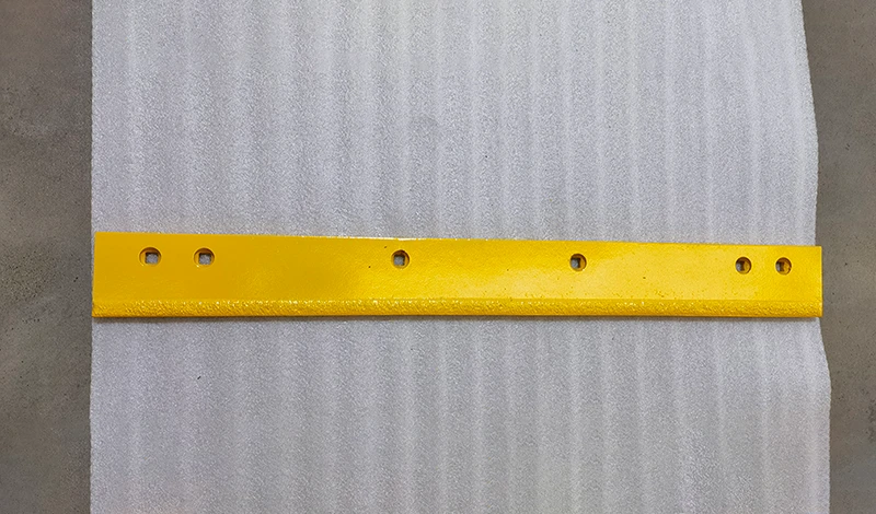
SENTHAI manufactures carbide snow plow blades and cutting edges for highway and municipal duty in Rayong, Thailand, with automated induction brazing for the insert bond and fitment confirmed against the measured mounting pattern. The construction detail is described on the carbide blade page, and route-class selection is covered in selection by road class.
FAQ
What changes on a highway plow blade above 60 km/h?
Impact energy rises with the square of speed, so the same blade meeting the same raised joint absorbs disproportionately more at 90 km/h than at 60. Section thickness, insert retention and braze toughness matter more than abrasion resistance at that point.
Does a thicker edge always last longer at highway speed?
Thicker sections resist the local deformation that precedes insert loss, but thickness does not compensate for a brittle grade or a poor bond. On routes with few raised structures, an over-thick edge adds weight and cost without changing the failure mode.
How do I know whether speed or abrasion is wearing my highway edge?
Speed produces sudden failures concentrated where the route presents structures or raised ironwork. Abrasion produces gradual wear distributed along the edge. The two leave different records on the same blade.
Can a highway fleet run one edge specification for every unit?
Only where the units work comparable surfaces at comparable speeds. A shoulder machine and an expressway machine on the same class of road can still see different impact exposure, which is why per-route measurement beats a fleet-wide part number.
Send the route, the working speeds and the failure pattern you are seeing. The SENTHAI engineering desk will confirm the section, the grade intent and the hardware for a high-speed duty cycle.