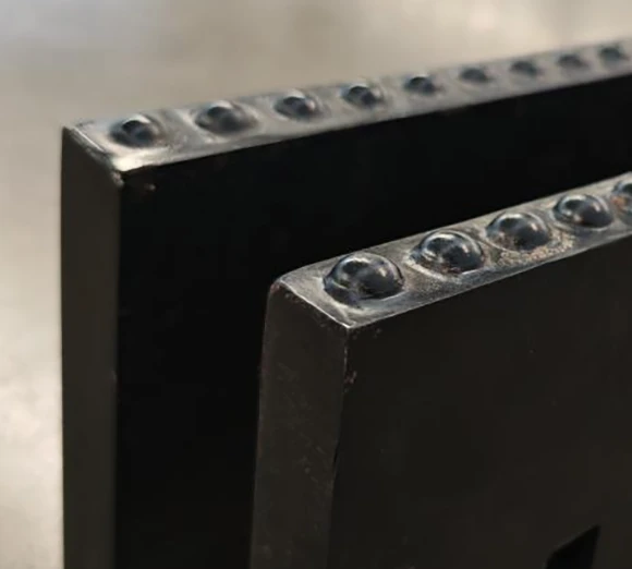
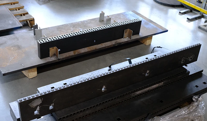
An edge that was specified as a carbide and cover assembly comes back with the carbide intact, the cover worn through and the carrier behind it distorted. The cover did its job and the carrier did not, because the two were treated as separate parts rather than as one load path.
A two-layer edge is a system: the cover absorbs impact, the carbide resists abrasion, and the carrier carries both. This article works through the load path, the fastening detail, the wear sequence and the situations where a cover is simply not needed.
What the cover edge actually protects
The cover absorbs impact so the carbide can resist wear.
A wear cover sits above the cutting edge to take the strikes that would otherwise reach the carrier and the insert bond, which keeps the carbide doing the one job it is suited to.
The distinction matters because buyers often assume the cover protects the carbide tip. It does not: the carbide is the wear surface, and the cover protects the structure behind it. The impact a plow edge meets on a real route arrives at the area just above the scraping line, not at the line itself, and that is the zone a cover occupies.
Covered assemblies therefore change two things at once. The carrier and the insert bond see less impact, which reduces debonding and distortion; and the wear surface becomes two parts with different roles, which means the cheaper part is the one that gets consumed. On a route with exposed joints and berms, that division is what keeps a carbide edge in service to the end of its wear life rather than retiring it early with intact inserts and a bent carrier.
Load paths through a two-layer edge
Adding a cover adds a second load path, and the way those two paths share load decides how the assembly behaves. The base edge takes the scraping load at the contact line; the cover takes the impact above it and spreads that load into the carrier; the fasteners hold both against the moldboard.
Three conditions keep the sharing predictable. The two layers have to sit flat against each other, because a gap concentrates load on the bolt line instead of distributing it. The cover has to be stiff enough to spread an impact rather than deflecting into the base edge. And the combined section has to remain within what the mounting expects, because a two-layer edge is thicker than the single edge it replaced and changes the geometry of the assembly.
Where an assembly is being specified from scratch, the useful questions are what the cover is expected to absorb, how that load reaches the carrier, and what happens to the fasteners when it does. The mechanical properties behind those claims are measured with the published test methods maintained by bodies such as ASTM International, and the standards work of AASHTO is the usual reference for edge and bolt patterns in North American highway practice.
Fastener spacing and clamping force
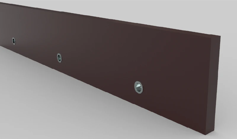
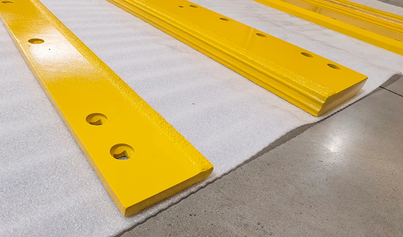
Fastener spacing does more work in a two-layer assembly than in a single edge, because the fasteners have to hold two parts together as well as hold the assembly to the machine.
Two failure modes follow from getting it wrong. Spacing that is too wide lets the cover lift between the bolts, which shows up as fretting and as a polished line along the carrier. Clamping force that is too high deforms the cover and pinches the layers, which distorts the wear line and can crack the cover at the holes over a season.
The specification should state the fastener grade, the hole diameter, the tightening sequence and the torque value, and it should say where the cover and base are clamped together rather than to the moldboard alone. Confirming torque after the first shift is standard practice for good reason: a new assembly beds in, and the figure that was correct at fitting is rarely correct after a few hours of work.
Wear sequencing between cover and base edge
The cover should reach its limit first. That is the design intent, and it is also the cheapest outcome, because the cover is the simpler part to replace and the one whose failure does not remove the edge from service.
Watching the sequence is a useful diagnostic. If the base edge wears faster than the cover, the cover is sitting too high and never contacting the road, or it is too thin to protect the carrier. If the cover wears in isolated patches rather than evenly, the layers are not flat against each other or the fasteners are not holding the two together along the length.
Where an assembly has been in service for several seasons, the wear sequence also indicates whether the replacement interval should be split. Replacing the cover more often than the base edge is normal on abrasive routes and is the reason the two parts are ordered separately rather than as a sealed unit.
Clearance and ground-following behaviour
Adding a cover changes the thickness at the wear face, and thickness changes how the assembly follows the ground. A two-layer edge sits lower in relation to the moldboard unless the shoe setting or the mounting is adjusted to suit.
The consequences appear quickly in use. An assembly that runs too deep loads the edge, raises scraping pressure and increases the impact it takes; one that runs too high leaves material behind and forces the operator to press down. Both outcomes are misread as blade problems rather than as a setting problem.
The fix is to re-establish the working height when the cover is fitted, using the same method that would be used for a new edge: set the shoes or skids, check the assembly on the surface it works on, and confirm the blade can still follow the surface rather than riding over it. On machines with limited clearance, this is the constraint that decides whether a cover can be used at all.
Replacement practice at change-out
Change-out is where a two-layer edge gives back the money it cost. The discipline is to treat the cover and the base edge as separate consumables with separate intervals, and to inspect the carrier whenever the layers come apart.
At each change-out, check the base edge for wear at the contact line and for distortion; check the cover for wear pattern and hole elongation; check the carrier for fretting, cracking and flatness; and check the fasteners for stretch and thread damage rather than reusing them indefinitely. Record the interval for each part separately, because a fleet that replaces the assembly as a unit loses the cost advantage it paid for.
Two practices make the records usable. Keep the batch reference with the unit so a premature failure can be traced, and photograph the wear pattern before the assembly is scrapped. The production controls and batch discipline behind those records are described on the SENTHAI quality control page, and a specific failure mode worth understanding before the next change-out is covered in the note on why carbide inserts come loose.
Deciding when a cover is unnecessary
A cover is not an upgrade in every application, and adding one where it is not needed creates its own problems. The decision follows the impact exposure of the route rather than the price of the edge.
| Condition | Cover recommended | Reason |
|---|---|---|
| Highway with bridge joints and berms | Yes | Impact reaches the carrier and the insert bond regularly |
| Abrasive chip seal, smooth surface | Optional | Low impact; the benefit is mainly spare capacity on the carrier |
| Gravel and mixed unpaved | Yes, with an impact-led grade | Stone strikes the area above the wear line |
| Machine with limited ground clearance | Only if height can be reset | Extra thickness risks losing ground following |
| Light seasonal work on smooth asphalt | Usually not needed | Impact exposure is low; the cover adds cost and weight |
Material behaviour behind these judgements, including how carbide grades and overlays differ in wear and toughness, is documented by producers such as Hyperion Materials & Technologies and Plansee, and the engineering standards for machinery interfaces are published by SAE International. The decision rule for a fleet is simpler: add a cover where impact, not abrasion, is retiring edges early, and leave it off where the assembly has room to work without it.
FAQ
What does a cover plate protect on a carbide edge?
It protects the carrier and the insert bond rather than the cutting tip. The cover sits above the wear face and takes the impacts that would otherwise reach the steel behind the carbide, which reduces the peel load on the braze or weld and limits distortion of the carrier. On abrasive routes it also spreads wear across a wider band, which keeps the insert line from becoming the only sacrificial surface.
Should the cover plate or the base edge wear out first?
The cover should be the part that reaches its limit first, because it is the cheaper of the two to replace and it exists to absorb damage. If the base edge or the carrier behind it is wearing faster than the cover, the specification is wrong rather than the wear being unlucky: the cover is too thin, too lightly clamped or positioned so it never contacts the road.
How tight should the fasteners be on a two-layer cutting edge?
Follow the drawing, because a two-layer edge needs enough clamp load to stop the layers moving against each other and not so much that the cover deforms. Use the specified grade and sequence, check torque after the first working shift, and expect the joint to settle slightly as the layers bed in. A cover that has moved is usually visible as polished marks around the holes or as fretting dust on the carrier.
When is a cover plate unnecessary?
It is unnecessary where impact exposure is low and the carrier is already protected by the edge geometry, and where the added thickness would interfere with ground following. Light seasonal work on smooth asphalt, and machines with limited clearance between the blade and the surface, fall into that group. On routes with bridge joints, berms and buried obstacles the cover earns its cost, because the damage it prevents is not wear but early failure.
Send the route conditions and the failures you saw last season. The SENTHAI engineering desk will confirm whether a covered assembly suits the machine, specify the cover and base edge as a pair, and quote the spare intervals with it.