A rigid carbide edge came off a county route after six weeks with three segments broken and the moldboard bowed behind the mounting line. The same route was then worked with a rubber-flex blade on the same truck class, and it finished the season with its segments worn and its mounting line straight. Nothing had changed except the base the carbide was carried on.
That difference is what a JOMA style blade is built around, and this guide follows the decisions a fleet has to take in order: what the design actually is, where it outlasts steel, what it cannot do, and where a rigid carbide edge remains the right answer.
What defines a JOMA style edge
The defining feature is the flexible base, not the carbide.
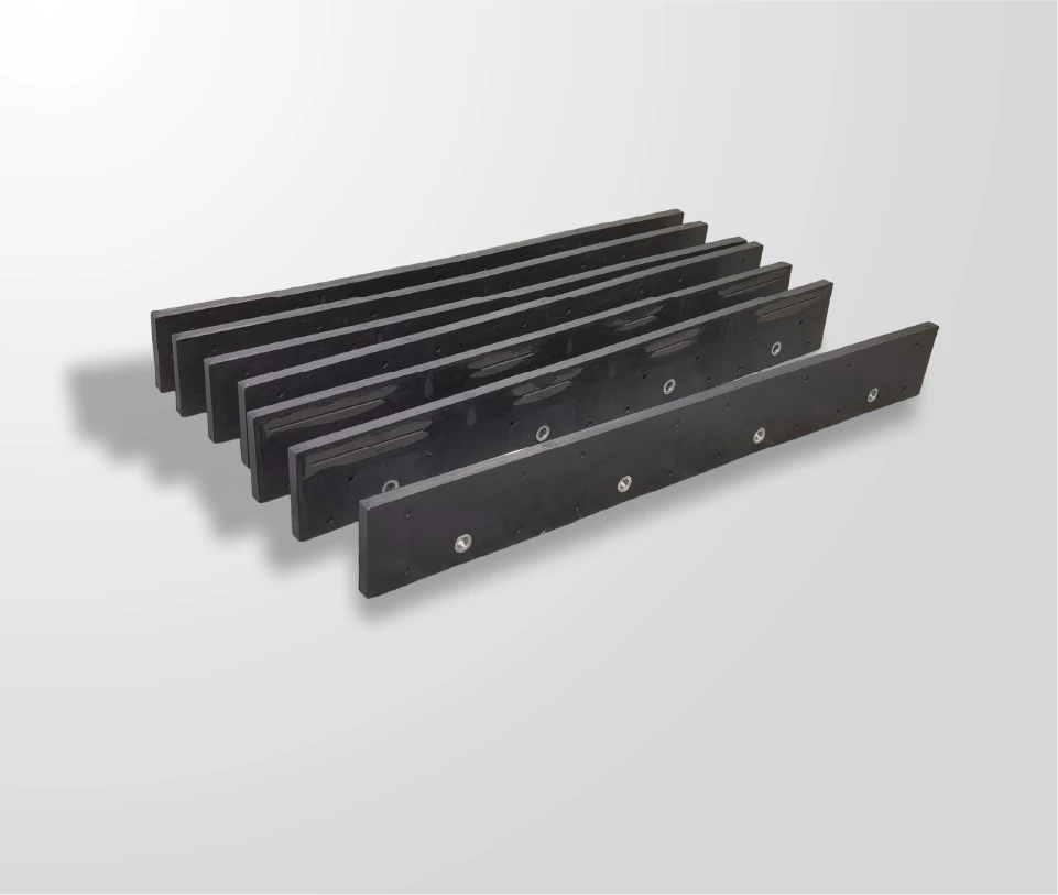
A JOMA style blade is a rubber or composite base carrying carbide wear segments along the cutting line, so surface conformity comes from the base and abrasion resistance comes from the segments.
That division of labour is what separates the design from a rigid edge with hard inserts welded into it. In a rigid assembly the cutting line is a single straight reference that either touches the surface or does not; in a flexible one, the base deforms locally so each part of the cutting line can follow the ground beneath it while the segments take the abrasion. The result is an edge that stays in contact across crown changes, patched sections and jointed surfaces without the operator correcting height every few metres.
The trade appears immediately and persists: a base that deforms absorbs load, which protects the machine and the surface, and also means the assembly cannot apply the concentrated pressure needed to cut a bonded layer. Deciding whether that trade suits the route is the first decision in the sequence. The range itself is described on the JOMA style blade page.
The rubber-flex base and carbide wear segments
The two materials in the assembly are chosen for opposite properties, and the design works because they are separated rather than blended. The base has to deform and return without taking a permanent set; the segments have to resist abrasion while staying fixed to something that is moving underneath them.
Two parameters describe the assembly in use. The first is the stiffness of the base at working temperature, because a base that stiffens in extreme cold behaves progressively more like a rigid edge. The second is the retention of the segments, because every segment is loaded by the base’s movement as well as by the road. That second parameter is why segment fixings are the part of the assembly that fails first when a machine is run with more down-pressure than the design expects.
Where the design outlasts steel edges
On rough and crowned surfaces, a flexible edge outlasts a rigid one for a structural reason rather than a metallurgical one. A rigid edge spanning a dip or a crown is in contact only at the high points, so the material it does touch carries the whole load and wears quickly while the rest of the edge does nothing. A flexible edge distributes contact across more of its length, so no single part carries a disproportionate share.
The effect is measurable in the wear pattern rather than in a headline figure: a rigid edge on a crowned road shows localised wear at the points that touched, while a flexible edge shows more even wear with damage concentrated where the route presents obstacles. That distinction is worth understanding before comparing service life, because the two edges are not failing for the same reason.
Surface tolerance and ground following
Ground following is the property the design is bought for, and it has a limit that rarely appears in a specification. A flexible base follows changes in surface height over its own length; it does not follow a change the whole blade meets at once, such as a raised manhole across the full width of the edge.
The practical reading of that limit is that the edge conforms to the profile of the road, not to every obstacle on it. It should be measured by what the cleared surface looks like after a pass: a consistent result across a crowned or patched section indicates the base is doing its job, while material left in a band across the whole width indicates a step that the blade met as a line rather than as a local change.
Load limits versus rigid edges
The load the assembly can transmit is set by the base, and it is lower than a rigid edge of the same width. That is a design consequence rather than a defect: the deformation that provides ground following also absorbs the force that a rigid edge would pass into the moldboard.
Comparing the two assemblies on this variable decides several other questions. Because the flexible base transfers less load, it also demands less of the mounting and puts less strain into the blade body — which is why the same truck that bowed a moldboard with a rigid edge can run a flexible one without distortion. The cost is that pressing the assembly against a bonded layer to cut it does not work, because the extra pressure is absorbed by the base rather than delivered to the surface.
| Variable | Rubber-flex base with segments | Rigid carbide edge |
|---|---|---|
| Contact across an uneven surface | High — the base conforms | Low — contact at the high points only |
| Load passed to the moldboard | Lower, absorbed by deformation | Higher, transferred directly |
| Cutting a bonded layer | Not effective — pressure is spread | Effective — pressure is concentrated |
| Surface damage risk | Low | Higher on soft or thin pavement |
| Repair practice | Replace the damaged segment | Replace inserts or the whole edge |
Segment spacing and coverage
Segment spacing sets how much of the cutting line is protected and how the load is shared between the base and the road. Closer spacing puts more carbide against the surface, which spreads the abrasion over more material and reduces the load on each segment; wider spacing concentrates the available carbide on fewer contact points.
Coverage also interacts with the base’s deformation. A segment that is asked to take load while the base beneath it is bending is being loaded in a way a segment on a rigid edge is not, which is another reason the spacing on a flexible assembly is not simply copied from a rigid one. Where a fleet runs both edge types on similar routes, the two specifications are best treated as separate rather than as two versions of the same edge — the comparison is set out in rubber-flex or carbide edge choice.
Applications that suit the design
The routes where the design pays are identifiable before purchase from three characteristics: the surface changes height under the blade, the surface itself is worth protecting, and the layer on top is not bonded to it.
In practice that describes crowned and patched secondary roads, unsealed roads and yards, paved surfaces in poor condition, and any route where the asset owner has asked that the surface not be scored. In all of those cases the flexible base is doing work that a rigid edge cannot do at any setting, which is a stronger argument than relative wear life. A workable rule is that a route which needs the edge to reach a bonded layer is not a candidate, and a route which needs the edge not to reach the surface is.
Where a rigid carbide edge is better
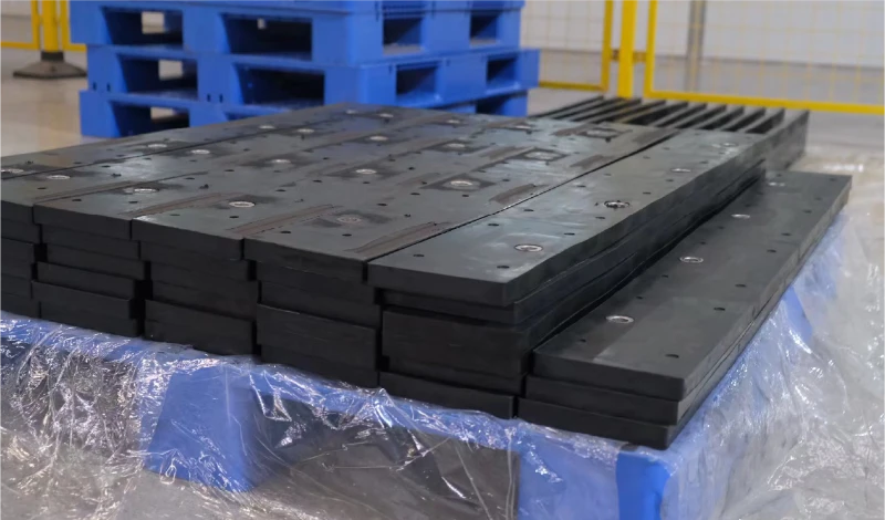
Rigid carbide wins wherever the objective is to remove a bonded layer rather than to clear loose material. On hardpacked routes, ice bonded to the pavement and refrozen ridges, the mechanism that matters is concentrated contact pressure, and a flexible base removes exactly that.
The second case for a rigid edge is a route where the surface can take localised pressure and where the fleet values a longer interval between changes over surface tolerance. That is the situation the comparison in the table above describes: the rigid assembly transfers more load, which is a defect on a weak surface and an advantage on a strong one.
A fleet that runs both is not hedging; it is matching the assembly to the mechanism on each route. The selection logic is the same one applied to road classes generally, where the deciding variable is the surface rather than the machine.
Reading the wear pattern on a rubber-flex edge
A flexible edge records its own operating history in the way its segments wear, and the patterns are specific enough to diagnose without a workshop.
- Even segment wear across the length indicates the base is conforming and the height setting suits the surface.
- Heavy wear on the outer segments points at a route worked with the blade angled hard against kerbs or banks.
- Segments missing while their neighbours are sound points at the fastenings rather than at the carbide, and usually at more down-pressure than the design expects.
- Wear concentrated in the middle indicates a crowned surface being loaded through the centre rather than evenly.
Reading the pattern before the season ends is what turns a replacement order into a specification decision. Health and safety guidance on operating this equipment is published by the Snow and Ice Management Association, and equipment practice by the Association of Equipment Manufacturers.
What the blade costs to run over a season
The cost case for the design rests on three lines rather than on the price of the blade: the segments consumed, the damage avoided on the surface, and the mounting repairs that do not happen.
The first line is measurable from the fleet’s own records, and it is usually close to a steel edge rather than dramatically better. The second and third are the lines that decide the comparison: a route where a rigid edge moves material into the verge every winter pays for the flex edge in re-grading, and a machine whose moldboard has been distorted by a rigid edge pays for it in workshop time. Both are visible in the fleet’s records over two seasons, which is the period needed to run the comparison fairly.
Winter maintenance research on equipment and surface interaction is published by the Transportation Research Board and the Federal Highway Administration, and material and hardness test methods by ASTM International.
SENTHAI manufactures JOMA style rubber-flex blades with carbide wear segments in Rayong, Thailand, with segment layout and mounting pattern set against the customer’s moldboard before production. The full range is listed on the snow plow blade hub, and fitting practice is covered in installing JOMA style segments.
FAQ
What is a JOMA style blade?
A snow plow blade built on a flexible rubber base with carbide wear segments along the cutting line. The flexible base follows an uneven surface while the segments do the wearing, which is why the design is common on crowned, patched and unsealed roads.
Is a JOMA blade better than a standard carbide edge?
It is better where the surface changes height under the blade and where the surface itself has to be protected. A rigid carbide edge is better where the blade has to cut a bonded layer, because a flexible base does not concentrate enough pressure to fracture hardpack.
How much load can a rubber-flex edge take?
The base deforms under load, so the assembly transfers less force into the moldboard than a rigid edge but also reaches its limit earlier. Running it with heavy down-pressure defeats the purpose and accelerates wear at the segment fixings.
Do the segments have to be replaced individually?
They can be, and that is one of the design’s advantages. Replacement is a matter of removing the damaged segment and its fixings, checking the faces of its neighbours, and re-torquing the joint.
Send the routes, the surfaces and the blade you run now. The SENTHAI engineering desk will confirm whether the flexible assembly suits the mechanism on each route and quote the segment layout against your moldboard.
This article is one step in the JOMA Style Rubber-Flex Blade Guide, which covers segments, clamps, insert retention and off-season storage.