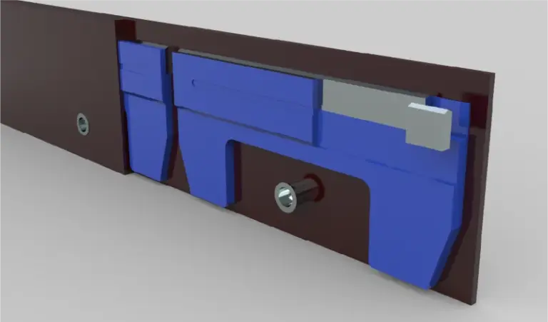
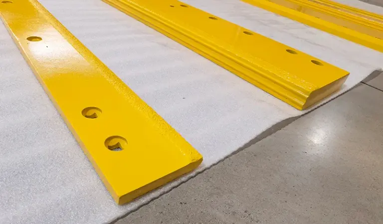
Size a two-piece motor grader edge by matching each half to the mouldboard end it bolts to: measure the mouldboard’s true length and end profile, record the existing bolt pattern (hole diameter, spacing, edge offset), then choose a left/right pair whose combined length covers the mouldboard without overhang and whose hole pattern matches the factory drilling. The split point and hole spacing matter more than nominal blade width.
Start from the mouldboard, not the blade label
Motor grader mouldboards vary in length, curvature, and end treatment, and a “two-piece” set is only two pieces because the machine was drilled for a split edge. Measure the mouldboard itself before looking at any catalogue number.
- Measure usable mouldboard length along the bottom, end to end, with the old edge removed.
- Record the end profile: straight, angled, or notched, and whether the outer ends are cut back.
- Note the mouldboard thickness and the bottom lip condition, since a worn lip changes how the edge seats.
If the old edge is still serviceable, lay it flat and measure it as a cross-check. A pair that was cut down in the field will not match the original drilling.
Record the bolt pattern before choosing a pair
The bolt pattern decides whether a two-piece edge fits at all. Hole spacing on grader edges is not universal, and a pair with the correct overall length but the wrong spacing cannot be installed without redrilling.
- Count holes per half and note which end carries the shorter spacing.
- Measure centre-to-centre spacing across at least three consecutive holes, then repeat at the outer end.
- Measure hole diameter and the countersink or plain-hole style.
- Record the distance from the top mounting face to the cutting lip (the edge height).
- Note left/right orientation and whether the halves are handed or symmetrical.
- Photograph the pattern with a tape measure in frame for the maintenance file.
Where the machine has been re-drilled, size to the current pattern rather than the original specification, and keep that record with the machine. Dimensions and hole spacing follow the product page specification for the edge family you select.
How the two halves divide the load
A two-piece edge is not simply one blade cut in half. The split is positioned so each half can be replaced independently, and the joint usually sits where the mouldboard sees less concentrated load.
| Check | What to confirm | Why it matters |
|---|---|---|
| Combined length | Left half plus right half covers the mouldboard bottom without overhang past the ends | Overhang catches pavement joints and kerbs |
| Split position | Joint aligns with the mouldboard’s centre drilling or the intended split point | Misaligned joints leave an uncovered strip |
| Handedness | Left and right halves are correctly identified | Reversed halves will not line up with the hole pattern |
| Edge height | Matches the machine’s original edge height within the allowed range | Changes attack angle and hardware length |
| Hardware | Plow bolts match hole diameter, countersink, and grip length | Loose or proud bolts wear and break |
If one end of a pair wears visibly faster, that is usually a machine or operating condition rather than a sizing error; the checks in one end of the edge wearing faster are the place to start before changing dimensions.
Carbide edges and the sizing margin
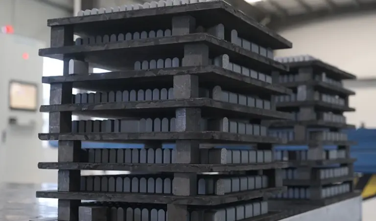
Carbide-tipped edges for snow plows and grader winter work are sized on the same mounting data as steel edges, but the wear allowance changes the decision. Carbide inserts sit at the lip, so the edge height and lip position must place the inserts where they contact the surface.
Because carbide wears differently from through-hardened steel, the practical service life depends on surface type, down-pressure, and operator technique. Expect a range rather than a fixed figure, and treat any single number as an estimate. The carbide snow plow blade range on the product page lists the available edge heights and hole configurations; select from those rather than assuming a custom drilling.
Cost also depends on how the machine is used: a pair that lasts a full season on one route may wear faster on abrasive milled surfaces. Compare cost per season, not cost per edge.
Field checks before the first bolt goes in
Dry-fit the pair before tightening anything. A two-piece set that fits on the bench can still bind on the machine if the mouldboard lip is worn or the ends are bent.
- Seat both halves against the mouldboard and confirm the joint closes without a step.
- Check that every hole lines up with light hand pressure; do not force bolts through misaligned holes.
- Confirm no part of either half extends past the mouldboard end.
- Verify bolt heads sit flush or below the wear surface.
Reversibility is a separate question from sizing: whether a given edge can be flipped depends on its hole pattern and countersink style, as covered in can you flip a cutting edge. If bolts are breaking rather than wearing, photograph the failure pattern before changing the edge size, following the practice in why plow bolts break.
Quick summary
Size a two-piece grader edge from the mouldboard length, end profile, and existing bolt pattern, then confirm the split position, handedness, edge height, and hardware match. Nominal blade width is the least useful number in the decision. Dimensions and hole spacing follow the product page specification.
Sources checked on 2026-11-08: SENTHAI Tools product specification page for carbide snow plow blades (/snow-plow/carbide-snow-plow-blade/); SENTHAI workshop notes on edge wear, reversible edges, and bolt failure (/talk/).
Three more perspectives
Limits
This page covers sizing logic for two-piece motor grader edges and does not provide machine-specific dimensions, torque values, or drilling drawings. It is not a substitute for the machine manufacturer’s mounting specification or the product page data for the selected edge family.