Take two edges cut to the same working width, one built with 40 inserts and one with 60: the second applies less load at each contact, and it also leaves less steel exposed between them. That trade sits at the centre of every spacing decision, and it is settled by the surface the edge works rather than by a figure that can be copied from another fleet’s drawing.
This guide works through the order the decision is actually made in: what coverage against per-insert load means, how pitch and insert width together set the contact pattern, how the choice changes between high-speed work and ice work, the conflicts that arrive from bolt patterns and blade ends, and the checks that keep a delivered edge matching the specification.
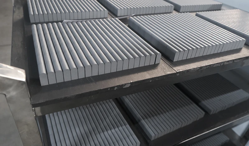
Coverage versus per-insert load
Spacing sets two quantities at once, and they move in opposite directions. Widening the pitch reduces the number of inserts on the edge, so each remaining insert carries more load and more steel is left exposed between contacts. Tightening the pitch does the reverse on all three counts.
Reading that as a trade rather than a preference is what makes the decision tractable. The table below sets out the direction each change moves in, alongside what the fleet is buying with it.
| Change | Effect on the edge | What it buys |
|---|---|---|
| Tighter pitch | More inserts, lower load each, less steel exposed | Better ice penetration at low down pressure |
| Wider pitch | Fewer inserts, higher load each, more steel exposed | Lower parts cost and more body material carrying abrasion |
| Uneven pitch | Load concentrates where the pitch is tightest | Nothing: it usually creates the uneven wear it was meant to cure |
| Constant pitch, adjusting insert width | Contact area changes without changing the count | A second lever when the count is fixed by the bolt pattern |
The fourth row is the one fleets forget. Where the number of positions is fixed by the body, the contact pattern can still be adjusted by changing the insert size, which avoids reopening the body design to solve a coverage problem.
How spacing and insert width set the contact pattern
Coverage along an edge is not a single number. It is the relationship between three dimensions: the pitch between insert centres, the width of the contact each insert presents to the road, and the relief or rake that governs how the insert meets the surface. Those three decide whether the edge behaves as a continuous cutting line or as a row of separate teeth.
Where the inserts are wide relative to the pitch, the contact effectively overlaps into a continuous line and the edge scrapes. Where they are narrow relative to the pitch, the contacts are separated and the edge works more like a set of cutters, which concentrates pressure but leaves the steel between them carrying abrasion. Both patterns are legitimate, and which one is wanted follows from the surface rather than from a preference for a smoother or a more aggressive cutting line.
Carbide insert spacing: setting coverage along the cutting edge
Set the pitch from the duty, then hold it constant.
Spacing is chosen by matching the contact pattern to the surface the edge will work, and then holding that pitch constant across the full cutting width. The surface sets the pressure needed at each contact, the machine’s down pressure sets how much is available, and the insert width sets how that pressure is spread.
A pitch that suits one of those inputs but not the others produces an edge that either rides over the material or cuts too deeply into the pavement.
The practical starting point is the failure mode of the previous edge. An edge that wore the steel between inserts faster than it wore the inserts themselves had too wide a pitch or too narrow a contact. An edge whose inserts chipped or whose cutting line sat too deep had too tight a pitch for the down pressure available. Reading the previous season’s edge this way gives a direction even when no measurement was taken.
Spacing on high-speed routes
Highway plowing at speed changes the spacing question because impact energy rises with speed and the consequences of a contact riding too low are worse. Two adjustments follow from that.
The first is that the edge generally runs a wider pitch with a broader contact, because the job at speed is to clear and cast rather than to break a bond, and a broader contact keeps the assembly from cutting into the pavement. The second is that insert positions near the ends of the working width need the most attention, since that is where a driver’s judgement has the least margin and where an impact with a pavement edge is most likely. The operating context behind these route decisions is described by the Federal Highway Administration.
Spacing for ice and hardpack work
Ice work pushes the decision the other way. Where the material to be removed is bonded to the surface, pressure at the contact is what breaks the bond, and pressure can only be raised by concentrating load. Tightening the pitch and narrowing the contact both raise it, which is why ice-oriented edges look more closely set than highway-oriented ones.
The limit is the pavement. Beyond a certain point, the pressure that breaks ice also begins to damage the surface it is protecting, and the machine’s down pressure becomes the constraint rather than the insert pattern. Where a machine cannot be adjusted to reduce down pressure, the honest answer is often a different edge for ice duty rather than an attempt to make one edge do both jobs.
Edge effects at blade ends
The ends of a plow edge wear differently from the middle, and the reason is mechanical rather than a manufacturing defect. As the blade is angled, the leading end presents a different relationship to the road than the trailing end, and both differ from the middle of the working width. Down pressure is also rarely uniform across a wide blade.
How the insert pattern is resolved at the ends is therefore a decision in its own right. The two workable approaches are to hold the pitch constant to the edge of the pattern and let the end insert take the additional wear, or to place a tougher insert at the ends so the pattern survives the shock loads that arrive there. What does not work is closing the pitch at the ends to add support, because the resulting tighter section then wears faster than the rest and the blade reports as uneven.
Spacing and bolt pattern conflicts
Most spacing compromises on real edges come from the bolt pattern or the segment joints rather than from the surface. Insert positions and fixing positions compete for the same steel, and where a plow edge follows a standardised bolt pattern there is only so much freedom left for the insert layout.
The resolution that causes the least trouble later is to treat the bolt pattern as fixed and the insert pitch as the variable, and where the two genuinely cannot be reconciled, to accept a smaller number of insert positions rather than a varying pitch. A slightly sparse but uniform pattern wears predictably, where a pattern that varies to dodge the fixings concentrates load and creates local hotspots that will be misread as a grade problem.
Cost per metre implications
Insert density is a direct multiplier on parts and on the time taken to fit them, so it belongs in the same conversation as grade. Rising density increases both, and the question is whether the extra contacts reduce the number of service events over a season or simply make each event more expensive.
Where they do not reduce service events, the same money usually buys more life by moving to a tougher or harder grade, because grade changes the wear rate while density changes the amount bought. The inputs needed to run the comparison are listed on the cost per mile inputs page, and the way grade and spacing interact is set out on the grade, size and spacing page.
Inspection of spacing after service
Spacing is easy to inspect once an edge has been in service, and the inspection is worth doing in a fixed order so that its result can be compared with the previous season.
- Measure the pitch at several points along the edge rather than at one, and check whether it is constant.
- Measure insert height at the same points, so pitch and wear can be read together.
- Record which positions wore first, and whether they sit next to a fixing or a segment joint.
- Note any insert that has moved or rotated in its pocket, since that changes effective pitch in service.
The third step is the one that generates the next specification. Where the same positions wear first across two seasons, the pattern rather than the material is the cause, and the fix belongs in the drawing.
Setting spacing for a new edge: the work order
A spacing decision only becomes real when it is written into an order that a supplier can manufacture against. The sequence below is the one that avoids the common failure where a good decision is made and then lost between the drawing and the batch.
- State the working width and the surface the edge will run on.
- State the pitch and confirm that it is held constant across the width.
- State the insert width, height and profile, so the contact area is defined as well as the count.
- State the bolt pattern, and show how the insert layout resolves against it.
- State the tolerance that governs pitch position, since a pattern with no tolerance is an assumption.
- Require the delivered lot to be recorded against the drawing, so a repeat order can be compared.
Dimensional tolerances and drawing conventions of this kind follow the practice published by ISO and ASME, and the test methods behind any material claim made for the inserts are published by ASTM International.
Common spacing mistakes and how to spot them
The mistakes below account for most spacing complaints that reach a supplier as a material problem, and each one leaves a recognisable trace on the returned edge.
- Pitch that varies to avoid a fixing: visible as a tight cluster beside the fixing and uneven wear at that point.
- Pitch copied from another fleet’s drawing without matching the surface: visible as an edge that either rides over hardpack or cuts into pavement.
- Pitch tightened to cure a retention problem: visible as chipping rather than pulling out, because the load per insert never changed.
- Mixed insert heights in one row: visible as the tallest insert wearing fastest and standing proud at inspection.
The third entry is the most expensive, because it addresses the wrong mechanism and adds parts at the same time. Where inserts are being lost rather than worn, the fix belongs in the retention method, and the geometry decision that sits alongside it is compared on the trapezoid versus bullnose page.
SENTHAI manufactures tungsten carbide inserts and carbide plow edges in Rayong, Thailand, with pitch, insert size and bolt pattern confirmed against the drawing before production. Equipment standards that constrain what a blade assembly may be fitted to are maintained by SAE International, and research on winter maintenance performance across a road network is published by the Transportation Research Board.
FAQ
How far apart should carbide inserts be on a plow edge?
There is no universal figure, because pitch is set by the surface, the down pressure the machine can apply and the insert width. Closer spacing concentrates pressure and suits ice work on lighter machines; wider spacing leaves more steel carrying load between inserts and suits abrasive routes. The value has to be fixed against a duty, then held constant across the working width.
Does closer spacing always mean better performance?
No. Closer spacing increases the number of contacts and raises cost per metre in parts and fitting time, and it reduces the amount of steel available to carry abrasion between inserts. Beyond a point, the edge is spending money on additional inserts without changing how it clears the road.
Why does spacing change across the width of some edges?
Usually because the bolt pattern or the segment joints forced it, not because it was chosen. Where spacing narrows in one section, that section takes more pressure and wears faster, and the edge reports as an uneven-wear problem. Holding pitch constant and resolving the conflicts elsewhere is the better compromise.
Can spacing be changed on an existing edge?
Only where the pockets allow it. On a brazed edge the pattern is fixed at manufacture, and on a mechanically retained edge the pocket positions are fixed by the body. Changing density means a new body, which is why the pitch decision is worth getting right before the drawing is released rather than after the first season.
What does insert density do to cost per metre?
Density multiplies the insert count along the edge, so parts and fitting time rise roughly in step with it. Whether that is repaid depends on whether the extra contacts reduce service events or wear on the steel body. Where they do not, the same money usually buys more life by going to a tougher or harder grade instead.
Send the working width, the surface, the bolt pattern and the insert profile you are considering. The SENTHAI engineering desk will confirm the pitch, the insert size and how the layout resolves against the fixings.
This article is one step in the Carbide Insert Selection and Replacement Guide, which covers grade, geometry, spacing, fitment tolerance and the replace-or-re-plate call.