SENTHAI holds its insert dimensions to tolerances measured in hundredths of a millimetre, and at that scale the choice of grade, size and spacing decides what a snow plow edge does on glaze ice, on hardpack and on bare pavement. The three parameters are usually specified separately, and that is where most of the avoidable mismatches start.
This guide works through the decisions in the order an engineer actually makes them: what the insert contributes, how grade trades hardness against toughness, which geometry family suits which surface, how size and thickness are chosen, how spacing sets the pressure at the cutting line, and how all of it is written down so a repeat order arrives the same.
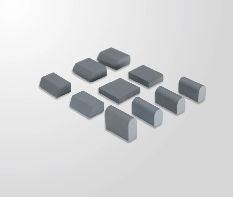
What an insert contributes to the cutting edge
An insert is the part of a plow edge that meets the road, and everything else in the assembly exists to hold it in the right place at the right angle.
That division of labour explains why insert specification matters more than edge thickness on abrasive routes. The insert carries the abrasive contact and concentrates down pressure into a small area, which is what allows an edge to bite into bonded snow without the whole assembly cutting into the pavement. The steel body absorbs impact, holds the mounting pattern and provides the stiffness that keeps the cutting line straight.
The practical consequence is that a change in insert specification changes the behaviour of the edge even when nothing else is touched. Moving from one grade to another alters how quickly the cutting line wears back; changing insert height changes how long the edge stays effective before the body starts to take the load. Neither change shows up in the part number of the blade itself, which is why they have to be recorded with it.
Carbide inserts: grade, hardness and toughness balance
Harder grades resist wear; tougher grades resist fracture.
Every carbide grade sits on that trade-off, positioned by grain size and binder content. A finer grain with less binder gives a harder material with higher wear resistance; a coarser grain with more binder gives up some wear resistance to absorb shock. Grade selection states which failure mode the route produces.
The way to read a route is to look at the wear pattern rather than the specification sheet. Inserts that come back polished and shortened have been worn; inserts that come back chipped, cracked or missing have been overloaded. Those two outcomes call for different grades, and a route that produces both usually needs the edge specified in sections rather than as a single part. The comparison between micro-grain and standard-grain material is set out on the micro-grain versus standard-grain page.
Hardness and toughness values for cemented carbide are reported against published test methods from ASTM International, and the material designations used across suppliers follow the conventions published by ISO. Asking for the test method behind a grade claim is the quickest way to compare two suppliers on the same basis.
Insert geometry families
Geometry decides where the load concentrates, and two families cover most plow work. Each one presents the road with a different face and transfers load into the body differently.
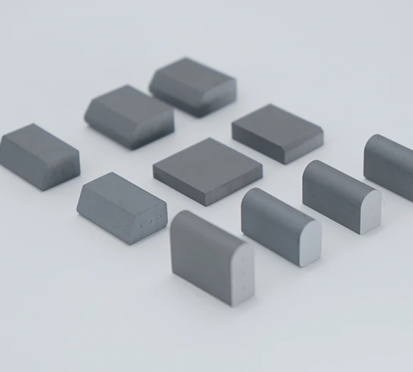
- Trapezoid inserts present a wide cutting face and a narrower base, which suits abrasive surfaces where the priority is carrying wear.
- Bullnose inserts present a rounded profile that concentrates pressure at a smaller contact area, which suits bonded ice and hardpack.
- Studded or segmented variants distribute the cut across several smaller points, which suits mixed surfaces where no single approach dominates.
The choice is not simply about performance on the ideal surface; it is about what happens on the worst one. An edge that runs mostly on pavement but meets a rail crossing twice a day is being asked to survive an impact load with a geometry chosen for abrasion, and that is the trade the shape decision has to account for. A direct comparison of the two main families is set out on the trapezoid versus bullnose page.
Size and thickness selection
Size and thickness decide how long the insert keeps the cutting line ahead of the steel, and how much material there is to wear before the body starts taking the load.
Height is the parameter fleets notice first, because it sets the service interval. A taller insert keeps the carbide contact further from the mounting line, so the edge stays effective for longer between changes; a shorter one saves material and cost on routes where the edge is unlikely to reach its wear limit anyway. Thickness works differently: it changes the insert’s resistance to bending and to chipping at the tip, which is why thicker sections are usually specified where impact is expected rather than where abrasion is heavy.
The constraint that ties size back to the machine is the plow’s own geometry. A taller insert extends the effective edge below the moldboard, which changes the attack angle and can push the blade beyond the adjustment range on some machines. Checking the available adjustment before increasing insert height avoids a specification that performs well on paper and cannot be set up on the truck.
Spacing and density along the edge
Spacing controls two things at once: how much pressure each insert applies, and how much steel is exposed between them. The two move in opposite directions, which is why spacing is a compromise rather than an optimum.
| Condition | Spacing effect | What it suits |
|---|---|---|
| Glaze ice, light down pressure | Closer spacing concentrates pressure at the cutting line | Machines that cannot apply heavy down force |
| Abrasive gravel or chip seal | Wider spacing leaves more steel between inserts | Routes where the body wears as fast as the carbide |
| Mixed surface, frequent impacts | Moderate spacing with a tougher grade at the loaded end | Edges that meet ironwork or rail crossings |
| Wide wing or underbody edge | Spacing held constant across the width | Keeping wear uniform along a long cutting line |
The last row is worth stating explicitly because it is a common source of uneven wear. Where spacing changes across a wide edge, the section with the closest spacing takes more pressure and wears faster, and the blade then reports as a design problem rather than a specification one.
Retention method choices
How the insert is held changes what the specification has to state, because a bonded joint and a mechanically fixed insert are inspected and replaced differently. A brazed insert makes the edge a single wearing assembly; a mechanically retained insert makes replacement a field operation and puts more weight on pocket or seat geometry.
For a purchase specification, the retention method belongs on the drawing with the insert details, along with the inspection that will be applied to the joint. That matters most on repeat orders, where a supplier change can quietly move an edge from one retention method to another while the insert itself stays identical. The mechanics of both methods are compared on the insert retention page.
Matching inserts to surface and speed
Surface and operating speed decide which of the two failure modes dominates, and the specification should follow that rather than a general preference for harder material.
- Bare pavement at moderate speed favours wear resistance; the insert is being abraded, not struck.
- Bonded ice and hardpack favour geometry that concentrates pressure, even where a softer grade is used to survive the impacts that come with it.
- High-speed route plowing at highway speed raises impact energy, which moves the specification towards toughness and towards thicker sections.
- Slow yard and ramp work allows closer spacing and a harder grade, because the impact energy involved is lower.
Operating practice for winter maintenance across a network is documented by the Federal Highway Administration, and equipment standards that constrain what a blade assembly may be fitted to are maintained by SAE International.
Grader and loader edges: same inserts, different duty
The same insert families appear on grader blades and loader bucket edges, and the specification logic transfers with one adjustment: the duty changes the balance between wear and impact rather than the fundamentals. A grader edge working a road crown is doing continuous, controlled abrasion, which favours wear resistance and even spacing. A loader edge working stockpiles meets mixed material at unpredictable angles, which favours toughness and a geometry that can survive an off-axis load.
Where a fleet runs both, standardising on a single insert across the two applications usually costs more than it saves. The parts may interchange, but the specification that suits one duty leaves the other either wearing too fast or chipping too often, and both outcomes show up as a complaint about the edge rather than about the insert.
Inspecting a delivery of inserts
Insert deliveries are worth a check at goods-in, because a dimensional drift that is invisible on the bench becomes a fitment problem across a whole blade. The check does not need to be elaborate: measure a sample across the critical dimensions, confirm the grade and batch identification against the order, and confirm that the insert seats in the pattern it was ordered for.
Two items belong with the delivery but are often filed and forgotten. The batch reference is what makes a later claim possible, and the inspection record is what shows the inserts were checked before they went onto an edge. Where a delivery is going into storage rather than straight onto a blade, the storage conditions in a workshop count too, since moisture held against brazed joints is a corrosion route rather than a wear one.
Purchase specification checklist
Writing the specification in a fixed order keeps a repeat order reproducible, and the steps below follow the decisions made earlier in this guide.
- State the primary duty: abrasion-dominated, impact-dominated, or mixed, with the surface named.
- Specify the grade with the property that matters most, and ask for the test method behind the claim.
- Name the geometry family and the insert dimensions, including height and thickness.
- State the spacing and confirm that it is held constant across the full working width.
- State the retention method, the joint inspection and the dimensional tolerance that keeps the fit repeatable.
- Require batch identification with the delivery, so the edge can be traced back to its production record.
Standards for brazing and for the inspection of brazed joints are published by the American Welding Society, and drawing conventions for calling out the dimensional requirements are published by ASME.
What the price of an insert actually buys
Insert price is a poor comparison on its own, because it sits inside a cost that is dominated by how often the edge has to come off the machine. An insert that costs more but keeps the cutting line effective for a longer interval can cost less per lane-kilometre than a cheaper one that shortens the interval, and the difference never appears on the parts invoice.
The comparison a fleet can actually make is between two specifications on the same route over a season: how much wear each one recorded, how many times the edge was serviced, and what the downtime cost in each case. That is a small amount of record-keeping, and it is the only way the grade and geometry decisions in this guide get tested against reality rather than argued about. Material documentation from carbide producers such as Plansee is a useful reference for reading the property data behind a grade claim.
SENTHAI manufactures tungsten carbide inserts, carbide plow edges and rubber-flex blades in Rayong, Thailand, with grade selection, insert geometry and spacing confirmed against the route conditions before production. The insert range is described on the carbide inserts page, and applications that need a specification built from the route rather than from a catalogue line can be discussed through the contact page.
FAQ
What does a carbide insert contribute to a snow plow edge?
It becomes the part of the edge that meets the road. The insert carries the abrasive contact and concentrates pressure at the cutting line, while the steel body around it absorbs impact and holds the mounting. That division of labour is why the insert specification decides how the edge performs and how often it has to come off the machine.
How do I choose an insert grade for a plow edge?
Start from the duty rather than from a grade chart. Abrasive surfaces with few impacts favour a harder, more wear-resistant grade; routes with raised ironwork and frequent impact favour one with more toughness. Where a route contains both, the specification usually splits along the edge rather than compromising on a single grade.
Does insert spacing change how the edge performs?
Yes, because spacing sets how much pressure each insert applies and how much steel sits between them. Closer spacing concentrates cutting action and leaves less steel exposed to wear; wider spacing leaves more of the body carrying load between inserts. The right value follows from the surface and the machine’s down pressure rather than from a single recommended figure.
Send the surface type, the operating speed, the machine’s down pressure and the edge geometry in service. The SENTHAI engineering desk will confirm the grade, insert size, spacing and retention method against the route.
This article is one step in the Carbide Insert Selection and Replacement Guide, which covers grade, geometry, spacing, fitment tolerance and the replace-or-re-plate call.