An insert that has “broken” usually came loose first. The carbide edge on a failed segment is often intact, the carrier shows the load mark, and the failure is in the joint or the fixing rather than in the material. That is why carbide insert retention is a design decision before it is a purchasing one.
This guide works through the loads an insert has to survive on a flex blade, how brazed and mechanical retention each carry those loads, the failure signatures that identify which method went wrong, and the documentation that makes a supplier’s claim verifiable.
Load cases that carbide insert retention has to survive
Four load cases arrive at the same joint, and they pull in different directions. Shear is the continuous sliding load along the wear face, which tries to drag the insert across its seating. Peel appears when the edge meets a raised joint or a stone and the load arrives at an angle rather than along the face. Vibration adds a high-cycle, low-amplitude load through the same interface for the whole shift.
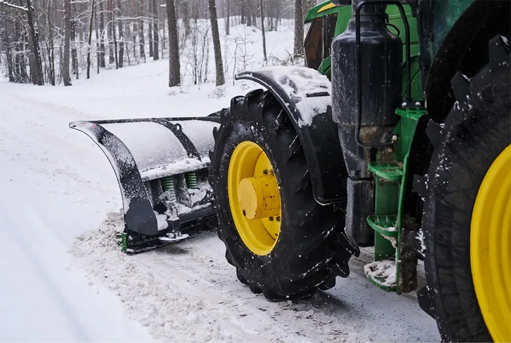
The fourth is thermal. Carbide and steel expand at different rates, so every temperature change, and every brazing cycle, loads the interface. On a flexible blade there is a fifth consideration that does not exist on a rigid plate: the base deflects under load, so the insert is carried through a small rotation rather than a fixed position. That movement is normal, and it is the reason the joint has to be specified for a service where the substrate is not perfectly rigid.
Brazed retention mechanics
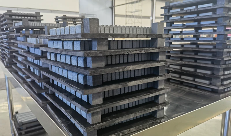
Brazing joins the insert to a steel carrier with a filler metal that melts below the melting point of either part, so the load is transferred through a continuous joint rather than through a set of contact points. When the process is controlled, the result is a joint that spreads shear across the whole seating face, which is exactly what a continuously abrasive duty needs.
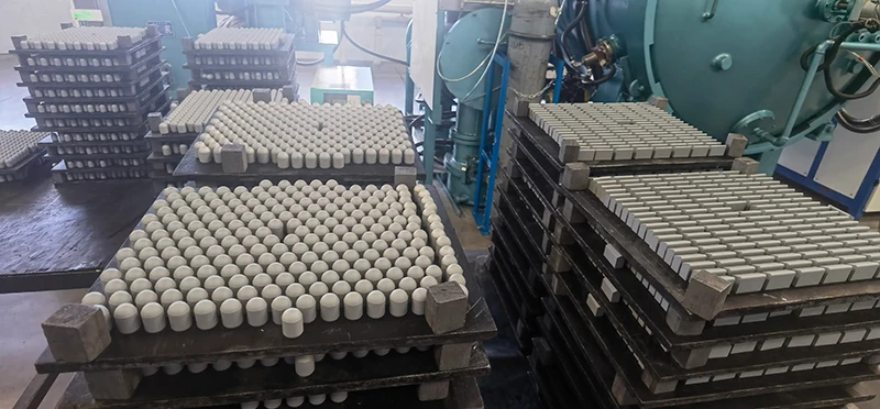
The strength of the joint depends less on the filler than on preparation and control. The surfaces have to be clean and correctly prepared so the filler wets them, the heat input has to be sufficient to flow the filler without overheating the carbide, and the cooling has to be managed so the joint does not carry excessive residual stress. Automated induction brazing exists because those three variables are easier to hold constant by machine than by hand, and the process is described on the site’s factory page.
Mechanical retention mechanics
Mechanical retention seats the insert in a feature that holds it in position and carries the load: a machined pocket, a clamp bar, a pin, or a screw fixing. The load path runs through the steel feature rather than a bond, which makes the assembly serviceable. An insert can be replaced in the field without a brazing set, and the carrier can be inspected directly when the insert is out.
The trade is in how the load arrives at the carbide. A fixing that contacts the insert at a point concentrates stress there, and carbide is unforgiving of point loading. Mechanical systems therefore need accurate pocket geometry, correct clamping, and a fixing that spreads load rather than concentrating it. Where those are right, the method tolerates impact well and survives the kind of damage that would crack a comparable brazed assembly.
Failure signatures for each method
The two methods fail differently, and the difference is visible in the parts after a loss. Reading the signature is what stops a fleet from changing the material when the problem is the joint.
| Observation | Likely method in use | What it indicates |
|---|---|---|
| Insert missing, filler traces left on the carrier | Brazed | Joint released; surface preparation, heat or filler coverage |
| Dark line along the joint before loss | Brazed | Partial bond, progressing to separation |
| Polished or fretted insert base and worn pocket | Mechanical | Movement in the fixing, loss of clamping |
| Insert cracked from the fixing point | Mechanical | Point loading on carbide rather than distributed support |
| Insert intact, carrier deformed around it | Either | Impact beyond the assembly’s design load |
Inspection and rework options
Inspection should match the method. For a brazed assembly, the practical checks are a visual assessment of the joint line, a tap test for a dull response that suggests an unbonded area, and a pull test on samples from a batch rather than on every insert. Where a producer has ultrasonic capability, joint inspection becomes measurable rather than comparative. For a mechanical assembly, inspection is simpler and more direct: check the clamping or fixing torque, look for movement marks in the pocket, and confirm the insert is seated without rocking.
Rework differs as well. A brazed insert that has released can be replaced on a sound carrier, but the surface has to be prepared again and the surrounding inserts checked for heat damage. A mechanically retained insert is usually a parts replacement, with the pocket assessed for wear before the new insert is fitted. Both paths depend on the carrier being sound, and the checks used before re-segmentation in rubber flex blade repair and re-segmentation apply here as well.
Choosing by duty cycle
The decision follows the duty rather than a preference. Where an insert is consumed by continuous abrasion at steady load, and the route offers few impacts, brazed retention distributes that load over the largest area and usually delivers the longest service interval. Where the route presents embedded stone, frost heave and joints, and where an insert damaged in service has to be replaced without returning the blade to a workshop, mechanical retention is the practical answer.
Mixed duties are common, and they are usually served by a hybrid: an insert located mechanically and bonded for load transfer, which keeps serviceability while distributing the shear. The same reasoning runs through the insertion of replaceable wear parts described in carbide snow plow inserts, and the failure modes that appear when retention is marginal are covered in the analysis of why carbide inserts come loose.
What to ask a supplier to document
Documentation is what separates a described capability from a controlled process, and five items answer the question for either retention method.
- The retention method, with the process parameters that are controlled and the range they are held in.
- The consumables: filler specification for a brazed joint, or fixing specification and torque for a mechanical one.
- The surface preparation or pocket tolerance, since both decide whether the load is distributed.
- The inspection method and the acceptance criterion, stated in measurable terms.
- The record that accompanies the batch, and how long it is retained.
Those items sit alongside the material and process standards published by bodies such as ASTM International and SAE International, and the production context for the components is published by manufacturers such as Hyperion Materials & Technologies. Fleet-level maintenance practice is covered by the Snow and Ice Management Association, the equipment view by the Association of Equipment Manufacturers, and the wider research by the Transportation Research Board.
The conclusion is that insert retention should be specified from the duty the blade will see, then verified with the process and inspection records that prove how it was made. On a flex blade the joint also has to tolerate a base that moves, which makes preparation and control more important than the name of the method. SENTHAI produces carbide inserts and flex blade segments in Rayong, Thailand, using automated high-temperature induction brazing with lot-level traceability across production batches.
FAQ
How are carbide inserts held in a flex blade?
Two methods dominate. Brazing joins the insert to a steel carrier with a filler metal so the load passes through a continuous joint. Mechanical retention seats the insert in a pocket, clamp, pin or screw fixing, so the load passes through the fixing rather than a bond. Some assemblies combine both, using a braze for load transfer and a mechanical feature for location.
Is brazed retention stronger than mechanical fixing?
Neither is stronger in general; they resist different loads. A sound braze distributes shear across the whole insert face, which suits continuous abrasion. Mechanical retention tolerates impact and is serviceable in the field, which suits routes where damage is expected and repairs are routine. The weaker option is the one applied outside the duty it was designed for. On a flex blade, the moving base makes preparation and control more important than the name of the method.
What does an insert that has come loose look like?
A brazed insert that has released usually leaves filler traces on the carrier and a clean insert face, and the loss is often preceded by a dark line along the joint. A mechanically retained insert typically shows a polished or fretted base, a worn pocket and, in some cases, a cracked insert where the fixing point loaded the carbide instead of supporting it.
What should a supplier document for insert retention?
The joining or fixing process with its controlled parameters, the consumables specification, the surface preparation, and the inspection method with its acceptance criterion. Then the records that show the inspection was performed for the batch supplied. A supplier that can describe the process but cannot produce the record is describing a capability rather than a controlled one. Ask for the record set from a previous batch before placing the first order.
Send the segment drawing, the duty the blade sees and the failure you are trying to eliminate. The SENTHAI engineering desk will propose the retention method with its process parameters, quote the inserts or segments, and supply the inspection record with the batch.