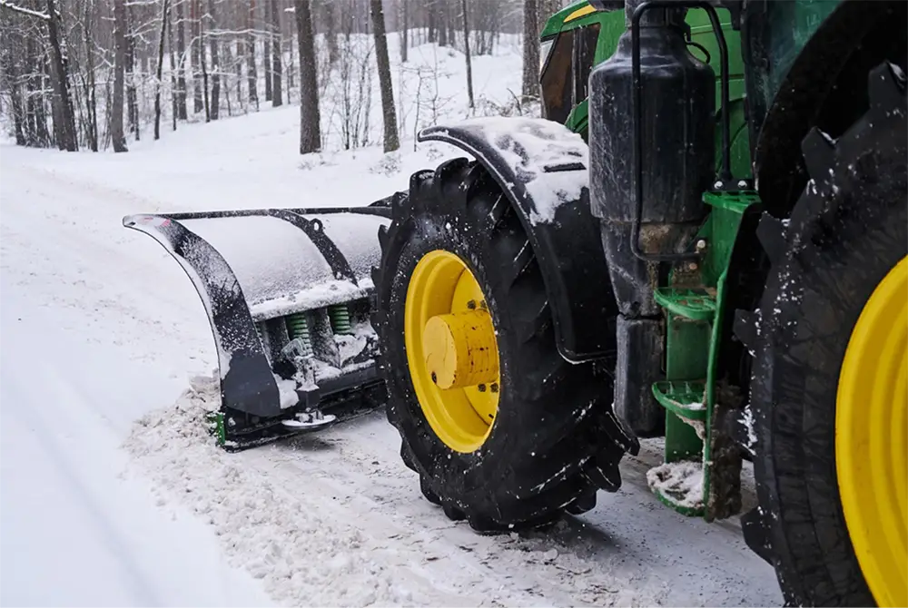
Four measurements decide whether a replacement edge fits, and three of them are routinely taken from the wrong place. Length is taken along the frame rather than the cutting line, thickness is measured at a worn end rather than at the hole line, and the bolt pattern is sampled at one pair of holes and assumed to be constant. The fourth, the wear allowance, is usually not taken at all.
This is the measurement sequence in the order it is best performed, with the checks that catch each of those errors. It closes with what to send in a request and how to verify a delivered edge against what was measured.
Why replacements arrive wrong
A replacement arrives wrong because the order carried a description of an edge rather than a specification of a machine, and the two are not the same thing. The most common failures are a pattern that varies along the width and was recorded as one pitch, a length taken from the frame rather than the cutting line, and a thickness taken from a worn section that no longer represents the part.
Each of those is a measurement taken from an accessible place rather than the correct one. The correct positions are not much harder to reach; they simply are not the ones a fitter naturally picks up when the machine is in the bay and the edge is still on it.
Measuring a snow plow blade: length, width and thickness
Measure from the cutting line, at the hole line.
The three basic dimensions each have a correct position. Length is measured along the working edge rather than along the frame, because the two differ wherever the frame is shorter than the blade it carries.
Height is measured from the mounting line to the current cutting edge, and on a worn edge that figure describes the wear rather than the part. Thickness is measured at the hole line, where the fasteners clamp, rather than at an end where the edge may have worn thin or deformed.
The table below sets out what each measurement decides, which is what determines how carefully it has to be taken.
| Measurement | Taken from | What it decides |
|---|---|---|
| Length | Along the working edge, both ends to the first hole | Whether the edge covers the working width and lands inside the frame |
| Height | Mounting line to cutting edge, on the part specified rather than the worn one | How much cutting material the new edge carries and how it sets up on the machine |
| Thickness | At the hole line | Whether the fastener length is correct and whether the assembly clamps as designed |
| Bolt pattern | Centre to centre between every adjacent pair, plus hole detail | Whether the edge bolts up at all |
Reading the third column explains the order of the sequence: the pattern decides whether the part can be fitted, and the other three decide whether the result works. A pattern error stops the job, while a height error produces an edge that fits and does not cut.
Bolt pattern and countersink
The pattern is the measurement that decides fitment, and it needs the treatment set out in full rather than a single figure. Number the holes from one end, measure between every adjacent pair, record the distance from each end hole to the end of the edge, and record the hole diameter and the countersink or counterbore form.
The end distances are the ones most often omitted and the ones that catch near misses, because a pattern can have correct spacing throughout and still be positioned differently relative to the ends. The countersink form decides whether the hardware seats flush, which is a fitment question that shows up later as loosening rather than as a part that will not fit. The full procedure for this is set out on the bolt pattern verification page.
Blade-to-moldboard interface
The interface between the edge and the moldboard is what the replacement has to sit against, and it is worth measuring even when it is not part of the order. Three conditions belong in the record: the flatness of the mounting line along its length, whether the frame has been deformed by impact, and whether the existing bolt holes show elongation.
Each of those conditions changes the result of fitting a correct edge. A bowed mounting line loads the new edge unevenly from the first shift; a deformed frame can leave a new edge standing proud at one end; and elongated holes mean the pattern will not locate the edge even if the replacement matches the original drawing exactly. Recording the interface is what allows a fitment problem to be separated from a supply problem after the fact.
Wear allowance and profile
Height has two different figures attached to it, and confusing them is the fourth measurement error. One is the current height of the worn edge, which is a wear measurement. The other is the height the replacement should have when new, which is a specification. The first describes what has been consumed; the second describes what is being bought.
The table below separates the two so the order carries the right one.
| Figure | Measured on | Used for |
|---|---|---|
| Remaining height | The worn edge, at several positions | Deciding whether the edge needed replacing at all |
| Specification height | The drawing or the machine’s manual | Ordering the replacement |
| Wear allowance consumed | Difference between the two | Forecasting the replacement interval |
| Profile or relief | The edge in place, viewed from the end | Matching the cutting geometry the machine was set up for |
The fourth row is the one that gets left out of an order entirely, because profile is hard to describe and easy to skip. A photograph of the end view, with the edge in place, resolves most of it.
Photographing and documenting
Photographs and measurements do different jobs, and a record with only one of them is incomplete.
- Photograph the whole edge in place, with a tape visible along part of the working width.
- Photograph the end view, which shows profile, relief and how the edge sits against the frame.
- Photograph the mounting interface with the edge removed, if the change is already under way.
- Record the measured figures in a fixed format, with the hole positions numbered to match the sketch.
- Note the machine, the working width and the date, since patterns and settings change over a fleet’s life.
The second item is the one that most often settles an order. Profile and relief are difficult to describe in words and obvious in a photograph, and a supplier can check a proposed replacement against the picture before it is made.
Common measurement mistakes
Four mistakes account for most replacement orders that arrive and do not fit, and each is a measurement taken from the convenient position rather than the correct one. Length taken along the frame rather than the working edge. Thickness taken at a worn end rather than at the hole line. Pattern recorded as a single pitch where it varies around a rib or a frame member. And height taken from the worn edge and used as the specification for the new one.
The third mistake is the most expensive, because it produces a part that is dimensionally plausible and wrong along its whole length. Where a pattern varies, the layout has to be recorded position by position, which takes longer and is the only record that can be reproduced.
Sending a complete request
A request that produces a fitting edge on the first attempt carries the following, in the order the supplier needs them.
- The machine type and the working width.
- The numbered pattern layout, with spacing between every pair and the end distances.
- Hole diameter and countersink or counterbore form.
- Edge length, thickness at the hole line, and the specification height.
- The profile or relief, described or shown in an end-view photograph.
- The material or wear allowance the edge is expected to carry.
The sixth item is the one that connects this order to the next one. An edge ordered with an explicit wear allowance can be compared against its own performance at the end of the season, which is what turns a replacement into a specification decision. Drawing conventions for recording dimensions this way are published by ASME and ISO.
Checking a delivered edge against the measurements
The receiving check is short and belongs before the machine is put out of service. Lay the edge on a flat surface, measure the hole positions against the numbered layout rather than against a pitch, confirm the hole detail at two or three positions, and check the end distances from both ends.
Then check the three dimensions that decide the result rather than the fit: length along the working edge, thickness at the hole line, and the height the edge presents when new. Where a delivered edge fails on any of them, the measured value against the stated requirement is what makes the notification actionable. The wear measurement that follows the edge through its life is described on the blade wear measurement page.
Measuring a rubber-flex or segmented edge
A segmented or flexible edge uses the same four measurements with one addition.
- The segment layout: how many segments the working width divides into, or the width available to be divided.
- The segment length and the fixing pattern within each segment, which differ from a one-piece edge.
- The joint positions relative to the ends of the working width, since a joint that lands on unsupported frame fails early.
- The backing condition, because a flexible edge depends on a straight backing for its geometry.
The third item is the one that decides whether a flexible edge behaves the way it did before. Rebuilding a width from a different number of segments changes where the joints fall, and a joint over an unsupported section of frame is the most common reason a replacement flexible edge performs worse than the one it replaced.
SENTHAI manufactures carbide and rubber-flex plow edges, wear plates and inserts in Rayong, Thailand, and produces replacement edges to a measured pattern with the layout confirmed against the customer’s machine. Equipment standards for the assemblies these edges fit are maintained by SAE International and the Association of Equipment Manufacturers, material specifications by ASTM International, and measurement questions on a specific machine can be raised through the contact page.
FAQ
What measurements do I need for a replacement plow edge?
Length along the mounting edge, height from the mounting line to the cutting edge, thickness at the hole line, and the bolt pattern with hole diameter and countersink form. A fifth input, the wear allowance or profile, sets how much cutting material the new edge should carry.
Should a worn edge be measured before or after removal?
Before, wherever it is practical, because the edge in place shows the interface the replacement has to match. Height measured on a worn edge gives a false figure for the new part, so record it as a wear measurement and take the length, thickness and pattern from the machine.
How precise does a plow blade measurement need to be?
Precise enough to distinguish a fit from a near miss, which for hole spacing means measuring each pair rather than sampling one. A pattern recorded to a single figure that turns out to vary along the width is the most common reason a correct-looking order arrives and does not fit.
Do I need to measure a rubber-flex edge differently?
The dimensions are the same, and the segment layout is an additional input. For a segmented or flexible edge you also record how many segments the width divides into, or the width available to divide, since two edges of the same length can be built with different segment counts.
Send the numbered pattern layout, the three dimensions and an end-view photograph. The SENTHAI engineering desk will confirm the pattern, the profile and the height the replacement should carry.