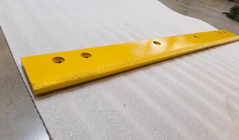
For snow plow blade bolt pattern: how to verify it before you order, the best result comes from matching the component, material, and setup to a documented operating condition, then validating fit, wear, safety, and cost in a controlled trial. This updated guide uses current search evidence and official-source checks to turn the topic into a repeatable selection process.
Updated: October 19, 2026
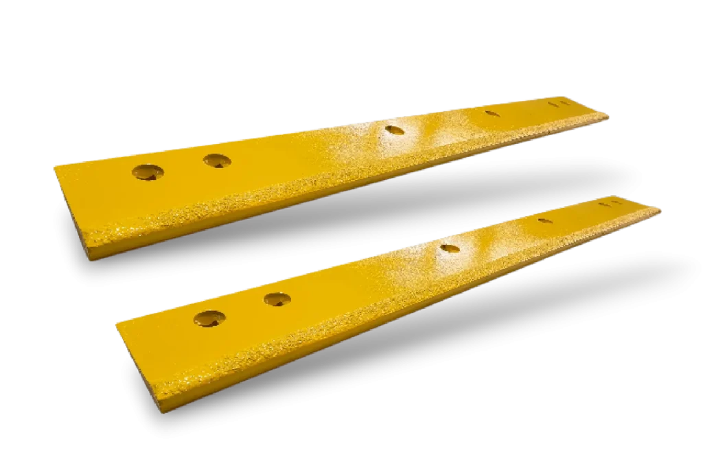
A pattern recorded as a single centre-to-centre figure is the most common reason a replacement edge arrives close but not identical, because that figure describes a uniform layout and most edges on real machines are not uniform. Ribs, frame members and end plates all force the spacing to change somewhere along the width, and the change is what a single number cannot capture.
This is the verification sequence to run before an order is placed. It covers how to measure spacing and hole detail, how to recognise the common families without relying on their names, how to document a pattern so that a supplier can reproduce it, and what to check when the edge is delivered.
Snow plow blade bolt pattern: why patterns go wrong on orders
Order from the pattern, not from the machine’s name.
Three things cause a pattern mismatch, and each of them is a shortcut taken at the enquiry stage. The first is quoting a family name rather than a measurement, on the assumption that the machine follows one family throughout; many do, and the ones that do not are the ones that produce a complaint.
The second is measuring the spacing between one pair of holes and treating it as the pitch for the whole edge. The third is leaving out the hole detail, which is where countersink form and diameter decide whether the hardware seats correctly.
The cost of a mismatch is not the edge; it is the machine being out of service while a second one is produced. That is why the verification takes an hour with the blade available, and why the record is worth keeping for the life of the fleet rather than only for the order in front of it.
Measuring centre-to-centre spacing
The measurement below produces a record that can be reproduced rather than a figure that has to be interpreted.
- Number the holes from one end of the edge, so every later measurement has a reference.
- Measure centre to centre between each adjacent pair, rather than sampling one pair.
- Note any position where the spacing changes, and what it changes around.
- Measure from each end hole to the end of the edge, so the pattern’s position is fixed as well as its spacing.
- Record the total working width so the layout can be checked against it.
The fourth step is the one most often omitted and the one that catches the near misses. A pattern can have correct spacing throughout and still be positioned a few millimetres off the end, which puts the last hole outside its clearance on the machine. Fixing the pattern relative to both ends removes the ambiguity.
Hole diameter and countersink detail
Hole detail decides whether the hardware seats, and it is where two edges that look identical on a bench differ. The table below sets out what to measure and what each measurement constrains.
| Feature | What to record | What it decides |
|---|---|---|
| Hole diameter | Measured value, and whether it is round or elongated | Whether the fastener passes and whether the pattern still locates |
| Countersink angle and diameter | The form and its measured size | Whether a plow bolt sits flush or stands proud |
| Counterbore depth, where used | Depth from the working face | Whether the head is protected from the road |
| Edge thickness at the hole line | Measured value | Whether the hardware length is sufficient |
The second row explains a failure that is often attributed to the bolts. A countersink at the wrong angle accepts a plow bolt far enough to tighten and not far enough to sit flush, and the proud head then wears or interferes in service. Recording the form rather than assuming it is what avoids the problem.
Patterns by common moldboard families
Several families of plow edge pattern are in wide use, and they interchange within limits rather than exactly. Family names are useful for shortlisting a supplier’s stock, and unreliable as a specification, because a pattern can belong to the same family and still differ in hole diameter, countersink form or end spacing.
The practical approach is to treat the family as a starting point and the measurement as the specification. Where a fleet runs several machine types, it is worth recording each pattern in the same format so the differences are visible on one sheet, which also shows where a single edge design could cover more than one machine and where it cannot.
Documenting the measurement
A pattern document that can be reproduced by someone who has never seen the machine contains four things: a numbered layout showing the spacing between each pair of holes, the distance from each end hole to the end of the edge, the hole detail from the table above, and the edge dimensions of length and thickness.
Two additions make it usable rather than merely complete. A sketch or photograph with the hole positions marked, so the numbers can be checked against a picture. And the date the measurement was taken, because an edge that has been run with elongated holes will measure differently from one that has not, and a later order should know which condition it is being made to match.
Tolerance and fit-up allowances
Even a correctly recorded pattern needs a tolerance, because a pattern made exactly to a nominal dimension and a machine that has been used will not agree perfectly. The table below sets out where the allowances belong.
| Feature | Allowance to state | Reason |
|---|---|---|
| Hole position along the edge | Tolerance on centre position | Absorbs accumulated variation without moving the pattern |
| Hole diameter | Small clearance over the fastener diameter | Allows fitting without reaming, and locates through the countersink |
| Edge length | Tolerance against the working width | Prevents the edge overhanging or falling short at the ends |
| Mounting line flatness | Stated limit | Ensures the edge seats along its length rather than on high spots |
Dimensioning practice of this kind follows the conventions published by ASME and the geometrical specification principles published by ISO. Stating the tolerance is what turns a measured pattern into a manufacturable one.
What to send with a quote request
The enquiry below gives a supplier everything needed to quote against a defined part rather than an approximate one.
- The numbered pattern layout, with spacing between every pair of holes and the end distances.
- The hole detail, including diameter and the countersink or counterbore form.
- The edge length, thickness and profile, and the material the edge is to be made in.
- The hardware the fleet uses, with its diameter and head form.
- A photograph of the edge in place with a tape measure visible across part of the pattern.
The fifth item is the cheapest check available. A photograph will not replace a measurement, and it resolves most of the ambiguity a written layout leaves, particularly where the pattern varies around a frame member or a rib. Where the edge is being ordered as part of a kit rather than on its own, the same inputs apply and the wider checklist is set out on the packed ice kit ordering page.
Verifying a delivered edge against the pattern
The receiving check takes minutes and should happen before the machine is taken out of service. Lay the edge on a flat surface, set a tape or rule along the mounting line, and check the hole positions against the numbered layout rather than against a pitch figure. Confirm the hole diameter and countersink form on two or three positions, and confirm the end distances.
Where an edge fails the check, the measurement and the layout position are what make the notification factual. A supplier can act on a measured deviation against a stated requirement; a description of a misfit usually produces a discussion instead. The receiving practice for loose components is described on the delivery inspection page.
Hardware that travels with the pattern
The pattern and the hardware are one decision, and ordering them separately is where fit-up problems reappear.
- Fastener diameter and head form, matched to the countersink.
- Length, sufficient for the edge thickness at the hole line plus the nut and any washer.
- Nut type, since the fixing used on a plow edge is not interchangeable with a standard nut.
- Quantity per edge, including any positions that take a different fixing.
The third entry is worth confirming rather than assuming. Hardware selection for these edges is set out on the conical nut and plow bolt page, and it is the point at which a correct pattern can still produce a poor fit.
When the pattern does not match any standard
A pattern that matches no common family is not a problem in itself; it only has to be measured and documented properly. The edge is made to the layout rather than selected from stock, and the sequence is the same as for any other order.
Two considerations are worth noting for an irregular pattern. The first is that the layout has to be recorded position by position rather than as a pitch, which means the record takes longer and is worth keeping permanently. The second is that a spare edge should be ordered from the same record rather than re-measured later, because an irregular pattern is exactly the case where a second measurement taken in a hurry produces a second variant. Standards for the assemblies these edges are fitted to are maintained by SAE International and the Association of Equipment Manufacturers, and material specifications by ASTM International.
SENTHAI manufactures carbide plow edges, packed ice kits and inserts in Rayong, Thailand, and produces edges to a measured pattern with the layout confirmed against the customer’s machine before production. Patterns that need to be recorded or checked against a drawing can be discussed through the contact page, and the fitment tolerances involved are examined on the dimensional tolerance page.
Match the Edge or Attachment to the Actual Operating Condition
This research-backed framework closes a recurring gap in pages ranking for snow plow blade: readers need a decision method, not a list of unsupported superlatives. Apply the same evidence fields to every option before choosing snow plow blade bolt pattern: how to verify it before you order.
| Decision gate | Evidence to collect | Release rule |
|---|---|---|
| Surface | Asphalt, concrete, gravel, pavers, bridge deck, or sensitive finish | Choose material and setup that protect the surface while meeting removal goals |
| Snow and ice | Loose snow, wet snow, compacted snow, bonded ice, or mixed conditions | Separate plowing, scraping, and deicing functions |
| Machine setup | Carrier weight, attack angle, down pressure, shoes, trip system, and speed | Verify the complete system rather than judging the edge alone |
| Validation | Short route trial, photographs, wear readings, fuel or time, and operator notes | Expand only after the trial meets a written acceptance rule |
The most useful choice is the one that meets the route objective without shifting damage or downtime elsewhere in the system. Record setup and operating conditions so the result can be repeated.
Run a Controlled Trial Before Full-Fleet Adoption
-
Freeze the baseline: record the current component, carrier settings, route, weather, operator, hours, and reason for removal.
-
Approve fit first: compare the supplier drawing with the machine and attachment. Do not drill, grind, weld, or substitute fasteners without an approved procedure.
-
Change one major variable: keep route and operating method as consistent as practical so the result can be attributed to the component rather than a different setup.
-
Inspect at planned intervals: photograph the same locations, measure wear, check fastener torque and retention, and log impacts or abnormal vibration.
-
Release against written criteria: decide in advance what wear, removal quality, downtime, and cost per operating hour would justify expansion.
Official-Source and SERP Verification
The technical boundary was checked against Federal Highway Administration snow and ice guidance. That source is used for the operating or safety context; model-specific dimensions, settings, and limits must still come from the approved manual for the exact machine and component. The following leading pages were reviewed for search intent and missing decision details:
Frequently Asked Questions
What should be verified before selecting snow plow blade bolt pattern: how to verify it before you order?
Confirm the exact application, dimensions, carrier limits, operating surface, expected impacts, supplier drawing, and acceptance evidence. A product name or grade label alone is not enough.
How should snow plow blade bolt pattern: how to verify it before you order be compared on cost?
Compare landed and installed cost, service hours, maintenance labor, downtime, collateral wear, and replacement reason. Use cost per operating hour for comparable routes rather than purchase price alone.
When is a trial required?
Use a controlled trial whenever fit, material, setup, route conditions, or supplier process changes. Define the baseline and pass criteria before the trial starts.
Which document controls installation and operating limits?
The current manual, approved drawing, and written instructions for the exact carrier and component control. General articles and cross-reference tables are screening tools, not installation authority.
Request an Application Review
Send SENTHAI the carrier or machine model, drawing or dimensions, operating surface, route condition, current failure mode, expected quantity, and target service interval. The engineering team can then review a suitable product path without changing the evidence requirements described above.