
For plow edge attack angle: setting blade pitch on fleet and contractor plows, the best result comes from matching the component, material, and setup to a documented operating condition, then validating fit, wear, safety, and cost in a controlled trial. This updated guide uses current search evidence and official-source checks to turn the topic into a repeatable selection process.
Updated: October 19, 2026
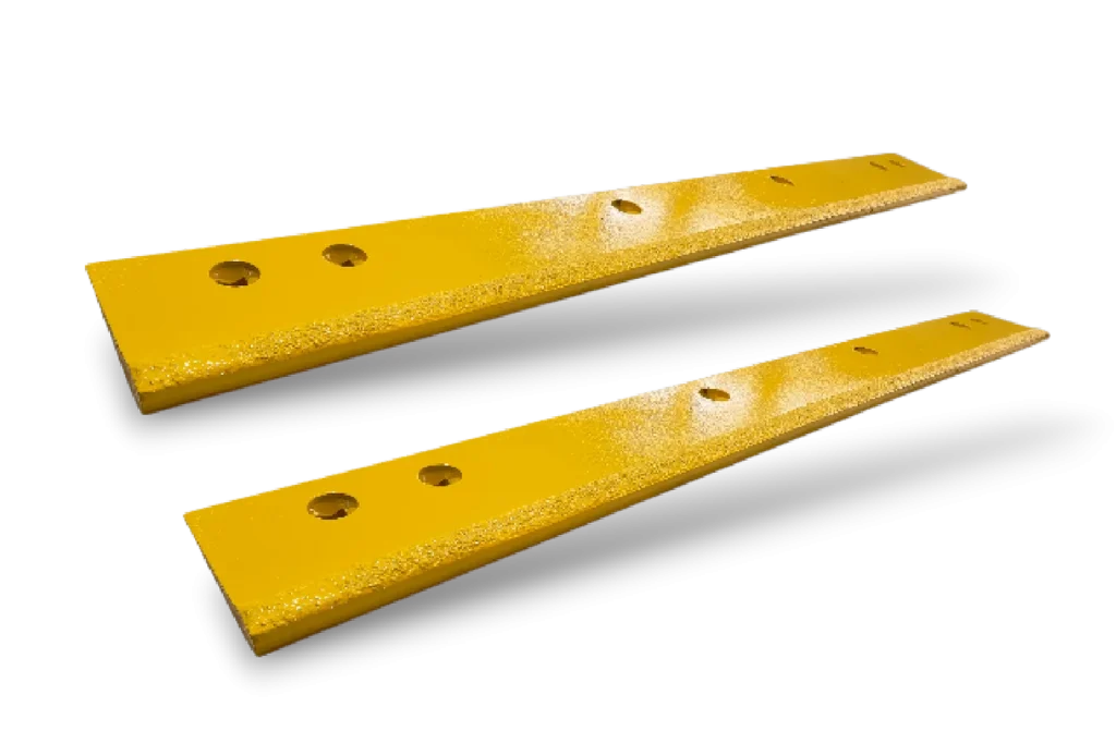
Two identical trucks on the same route, one with the blade set two degrees steeper than the other. Over a season the steeper blade consumed more edge on its leading face, needed more down-pressure to keep cutting and left a cleaner surface on the compacted sections. The shallower one wore more evenly and left a thin layer the operator had to work twice.
Neither setting was wrong; they were answers to different questions. This implementation path sets the blade angle as a routine: what the setting does, how to establish it, what to check after each step, and the mistakes that force the whole exercise to be repeated.
How attack angle changes scraping action
The angle decides whether the edge scrapes or bites.
A shallow setting lets the edge skim, removing loose material; a steeper setting drives the edge into the surface, which is what breaks a bonded layer but also raises the force needed to keep moving.
The mechanism is a change in the direction of the force the blade applies. At a shallow angle most of the machine’s push moves material forward; as the angle steepens, a greater share of that force is directed downward into the surface, which is why a steeper blade cuts harder and stalls sooner. Between the extremes there is a working band in which the edge marks the surface without stopping the machine, and on compacted or bonded ground that band is narrower than it is on loose snow.
The first decision in the routine is therefore to establish what the route actually requires: skim, cut, or break. A setting chosen for one of those and used on another is the most common reason a fleet concludes that its edge is at fault when it is not. Route-class selection is covered in blade selection by road class.
Effects on edge wear pattern
Wear pattern follows setting, and reading it is how a fleet confirms whether the angle is right without a trial. A shallow setting wears the underside of the edge and leaves the leading face comparatively untouched; a steep one wears the leading face and loads the fixings harder.
Two patterns indicate the angle is wrong rather than the material. Wear concentrated on the leading face with sound inserts underneath points at a setting steeper than the surface needs; wear spread across the underside with an intact face points at an edge that is being dragged rather than cutting. Both are cheaper to correct by adjusting the setting than by changing the specification. The classification used for insert edges, which applies in the same terms to a steel edge, is set out in reading carbide insert wear patterns.
Effects on casting distance and coverage
Angle also decides how far and how high the snow goes, because it changes the direction the material takes as it leaves the edge. A shallow setting keeps the material low and pushes it forward along the blade line; a steep one lifts it, which throws it further but also makes the windrow more sensitive to wind and to the shape of the verge.
The practical consequence for a route is that the setting has to suit where the snow can go, not only how hard the material is. A street with a narrow verge needs the snow kept low and directed, while a wide shoulder can accept a higher cast. That is why two routes worked by the same machine can legitimately carry different settings, and why the setting belongs in the route record rather than in a fleet-wide instruction.
Settings for flexible versus rigid edges
Flexible and rigid edges are not set to the same angle, because they reach the surface in different ways. A rigid edge has to be angled more steeply to keep contact across an uneven surface, since it cannot conform; a flexible base already follows the surface, so an equivalent angle simply loads the base and its fixings without improving contact.
| Question | Rigid edge | Flexible edge |
|---|---|---|
| Why the angle is needed | To hold contact across an uneven surface | Mainly to set the cast, not the contact |
| Effect of a steeper setting | Cuts harder, stalls sooner | Loads the base and the segment fixings |
| Wear that follows from too steep | Leading face wear, higher fixing load | Fixings work loose before the segments wear |
| Typical approach | Set on the route, record the value | Set at the minimum that gives the cast required |
The comparison between the families on a route is covered in rubber-flex or carbide edge choice. For the setting routine, the important point is that the two are established separately rather than by applying one value to both.
Adjustment range on common mounts
The mount decides how much adjustment is available, and the range is worth establishing before a setting is chosen so that the working value sits inside it rather than at an extreme. Two mount characteristics matter: how the angle is changed, and how much travel the mechanism has in each direction.
The check is a physical one. Move the blade through its full range on the machine, note the positions at both ends, then choose a starting point with adjustment available in both directions. A setting made at the end of the travel cannot be refined at the roadside, which is where refinement usually becomes necessary. Where the range proves too narrow for the routes, that is a mount question rather than a blade question and belongs in the specification.
Field test: measuring the difference
The field test establishes the value that the fleet then keeps, and it needs three items rather than a measurement programme: a marked section of route, a way of recording the setting, and a decision about what counts as a pass.
- Choose a section that represents the route, including its worst surface.
- Set the blade to a starting angle with adjustment available in both directions.
- Run the section at working speed and look at the cut line behind the blade.
- Adjust one notch and repeat; stop at the shallowest setting that gives a continuous cut line without stalling.
- Record the setting, the speed it was tested at and the surface it was tested on.
Stopping at the shallowest setting that works is the step that saves edge life, because every degree beyond that adds load without adding clearance. The pass condition is a continuous cut line; the failure condition is a polished strip with intermittent marks, which means the edge is skipping and the setting or the speed is wrong.
Who owns the setting
A setting that nobody owns drifts. The practical division is that the workshop establishes and records the value, the operator works within it and reports when it stops producing a cut line, and the supervisor decides when a route change justifies re-testing.
That division matters because the pressure to change a setting usually arrives from the cab on a bad night, and a change made then is not recorded. When the next person works the route, the machine carries an undocumented setting and the wear pattern that follows is attributed to the edge. Writing down who may change the value, and requiring a record when it happens, removes the ambiguity without preventing a sensible adjustment during a storm.
Documenting settings per vehicle
The record that makes this routine work is short, and it lives with the machine rather than in the office. Four fields cover it, and they are the same four needed at the next edge change.
- The attack angle setting and where it sits in the mount’s adjustment range.
- The surface and route section the setting was established on.
- The working speed it was tested at.
- The date and who recorded it, so a later change can be traced.
With those four on the machine, an edge change restores the setting rather than re-inventing it, and a wear complaint can be tested against the conditions the edge was actually working in.
| Recorded item | Used for | Lost when missing |
|---|---|---|
| Attack angle setting | Restoring the value at the next edge change | The setting is re-invented and the wear baseline moves with it |
| Position in the adjustment range | Knowing whether refinement remains possible | A setting at the end of travel is discovered on the route |
| Surface and route section | Testing a complaint against the conditions worked | Every complaint becomes an argument about the edge |
| Working speed at the test | Comparing settings fairly between machines | Speed differences are read as edge differences |
What changes the setting once it is fixed
A setting is not permanent, and knowing what legitimately changes it prevents both unnecessary re-testing and silent drift. Three events justify revisiting it: a change of surface type on the route, a change of edge family, and any impact that moved the mounting or the carrier.
What does not justify a change is a single difficult storm. An edge that has stopped cutting mid-season is more often worn to the point where its geometry has changed than wrongly set, and the first check should be the edge measurement rather than the angle. Equipment practice is published by the Association of Equipment Manufacturers, operator guidance by the Snow and Ice Management Association, and road maintenance guidance by the Federal Highway Administration.
Training points for operators
Training is what keeps a documented setting from being replaced by habit. Three points cover the part of the routine an operator controls.
- Recognise the cut line that the setting is meant to produce, and the polished strip that means it is not working.
- Know that pressing harder is the wrong response to skipping; the setting or the speed is the variable.
- Report a change rather than adjusting silently, so the record survives the shift.
Winter maintenance research on plowing practice is published by the Transportation Research Board, and component practice by AASHTO. SENTHAI manufactures carbide snow plow blades and cutting edges in Rayong, Thailand, and confirms the edge specification and recommended setting for the surface, the mounting and the blade family the customer runs. The range is on the snow plow blade hub.
Match the Edge or Attachment to the Actual Operating Condition
This research-backed framework closes a recurring gap in pages ranking for Plow Edge Attack Angle: Setting Blade Pitch on Fleet and Contractor Plows: readers need a decision method, not a list of unsupported superlatives. Apply the same evidence fields to every option before choosing plow edge attack angle: setting blade pitch on fleet and contractor plows.
| Decision gate | Evidence to collect | Release rule |
|---|---|---|
| Surface | Asphalt, concrete, gravel, pavers, bridge deck, or sensitive finish | Choose material and setup that protect the surface while meeting removal goals |
| Snow and ice | Loose snow, wet snow, compacted snow, bonded ice, or mixed conditions | Separate plowing, scraping, and deicing functions |
| Machine setup | Carrier weight, attack angle, down pressure, shoes, trip system, and speed | Verify the complete system rather than judging the edge alone |
| Validation | Short route trial, photographs, wear readings, fuel or time, and operator notes | Expand only after the trial meets a written acceptance rule |
The most useful choice is the one that meets the route objective without shifting damage or downtime elsewhere in the system. Record setup and operating conditions so the result can be repeated.
Run a Controlled Trial Before Full-Fleet Adoption
-
Freeze the baseline: record the current component, carrier settings, route, weather, operator, hours, and reason for removal.
-
Approve fit first: compare the supplier drawing with the machine and attachment. Do not drill, grind, weld, or substitute fasteners without an approved procedure.
-
Change one major variable: keep route and operating method as consistent as practical so the result can be attributed to the component rather than a different setup.
-
Inspect at planned intervals: photograph the same locations, measure wear, check fastener torque and retention, and log impacts or abnormal vibration.
-
Release against written criteria: decide in advance what wear, removal quality, downtime, and cost per operating hour would justify expansion.
Official-Source and SERP Verification
The technical boundary was checked against Federal Highway Administration snow and ice guidance. That source is used for the operating or safety context; model-specific dimensions, settings, and limits must still come from the approved manual for the exact machine and component. The following leading pages were reviewed for search intent and missing decision details:
Frequently Asked Questions
What should be verified before selecting plow edge attack angle: setting blade pitch on fleet and contractor plows?
Confirm the exact application, dimensions, carrier limits, operating surface, expected impacts, supplier drawing, and acceptance evidence. A product name or grade label alone is not enough.
How should plow edge attack angle: setting blade pitch on fleet and contractor plows be compared on cost?
Compare landed and installed cost, service hours, maintenance labor, downtime, collateral wear, and replacement reason. Use cost per operating hour for comparable routes rather than purchase price alone.
When is a trial required?
Use a controlled trial whenever fit, material, setup, route conditions, or supplier process changes. Define the baseline and pass criteria before the trial starts.
Which document controls installation and operating limits?
The current manual, approved drawing, and written instructions for the exact carrier and component control. General articles and cross-reference tables are screening tools, not installation authority.
Request an Application Review
Send SENTHAI the carrier or machine model, drawing or dimensions, operating surface, route condition, current failure mode, expected quantity, and target service interval. The engineering team can then review a suitable product path without changing the evidence requirements described above.