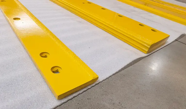
Size a bolt-on edge for a wheel loader by matching five dimensions to the bucket: bolt hole spacing (center-to-center), bolt diameter and grade, edge width and thickness, edge length and end configuration, and bevel orientation. Start from the bucket’s existing bolt pattern and the machine’s operating weight class, not from the old edge alone. The old edge tells you what was fitted; the bucket and the application tell you what should be fitted.
Start from the bucket, not the worn part
A worn edge has usually lost material and may have been re-drilled, shimmed or replaced with a non-original part at some point in its life. Treat it as a reference, not a specification. Measure the bucket’s bolt pattern directly and confirm it against the machine’s parts documentation.
- Bolt hole center-to-center spacing along the length, and the offset of any staggered holes.
- Bolt diameter and the counterbore or countersink geometry in the bucket lip.
- Bolt grade and thread pitch — mixing grades across a pattern causes uneven clamp load.
- Bucket lip thickness at the mounting face, and whether a wear strip or liner sits behind the edge.
Record these as a drawing, not as notes. A pattern that is 2–3 mm out over a 1.5 m edge will not pull down flat, and the gap becomes a fatigue initiation point. Check the drawing and hole layout on the product page before ordering.
The five dimensions that define fit
Most sizing errors come from treating length and width as the only variables. In practice, thickness and hole pattern govern whether the edge survives, while length and width govern coverage and penetration.
| Dimension | What it controls | How to establish it |
|---|---|---|
| Hole spacing (C-C) | Whether the edge seats flat | Measure the bucket lip; check for staggered or double patterns |
| Bolt diameter and grade | Clamp load, joint integrity | Match bucket counterbore; confirm grade from machine data |
| Edge width (face height) | Wear allowance, bucket capacity | Original spec, adjusted for application and material density |
| Thickness | Stiffness, wear life, weight | Machine weight class and abrasiveness of the material |
| Length and ends | Coverage, corner protection | Bucket width; whether a center section and two end bits are used |
Thickness and width trade against each other. A wider face gives more wear allowance but adds weight and can reduce penetration in compacted material. There is no universal correct combination; it depends on the duty cycle.
Sectional versus one-piece edges
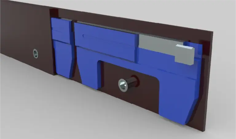
Wide loader buckets are commonly fitted with a three-piece arrangement: a center edge plus two bolt-on end bits, or a segmented edge in several sections. This affects sizing because each section is specified separately and the joints must align with the bucket’s pattern.
Sectional edges cost more per kilogram in manufacturing and add joint complexity, but they let a fleet replace only the worn portion and reduce handling weight during service. One-piece edges are simpler to specify and fit, but a worn corner means replacing the whole part. For fleet buyers, the decision is usually driven by how the machine is actually used — corner-heavy work in abrasive stockpiles tends to favour sectional arrangements.
Material, hardness and bevel
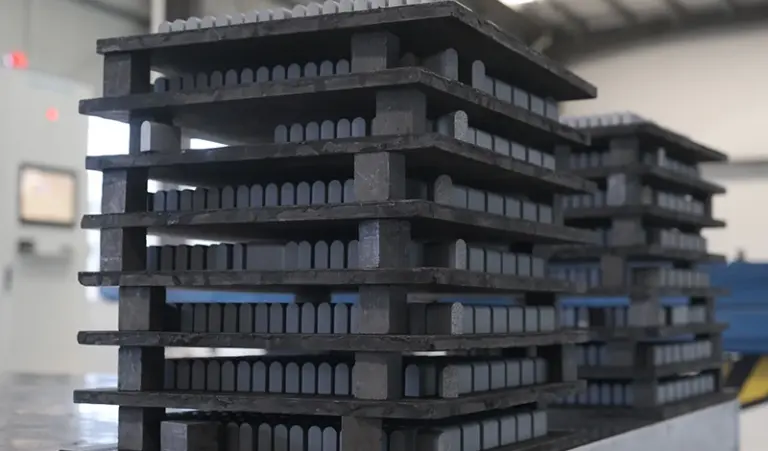
Cutting edges are typically supplied in through-hardened or heat-treated boron steel, with hardness in a broad range depending on supplier and grade. Harder edges resist abrasion but are less tolerant of impact; softer edges roll and peen rather than crack. The right balance depends on whether the machine works in sand and gravel or in broken rock and demolition debris.
Bevel orientation matters as much as bevel angle. A bevel that faces the wrong way relative to the bucket’s original design changes the cutting geometry and load path. Confirm bevel direction and angle against the machine specification, and confirm whether the edge is intended to be flipped for a second wear life.
Bolt torque, re-torque and the failure mode to watch
Most edge failures that are blamed on the part are joint failures. Loose bolts allow relative movement, the hole elongates, the edge rocks, and cracks start at the hole. Torque values depend on bolt diameter, grade and lubricant, so take them from the machine manufacturer rather than from a generic table.
Plan a re-torque interval after the first hours of operation, then at scheduled service. Photograph any failed joint before repair — bolt condition, hole elongation and fretting marks on the mounting face all indicate whether the cause was torque, pattern mismatch or operating abuse. Our note on why plow bolts break and what to photograph sets out the evidence worth capturing.
The commercial side: specification risk and supply
For a distributor or fleet buyer, the cost of a wrong edge is rarely the price of the part. It is the machine downtime, the second freight movement and the labour to fit and remove it. Specification risk is therefore the main commercial variable, and it is reduced by confirming the hole pattern and thickness before the order is placed.
- MOQ: depends on the section type and whether the item is a stock pattern or made to drawing; non-standard patterns usually carry a higher minimum.
- Lead time: stock patterns ship in weeks; made-to-pattern edges depend on material availability and heat-treat scheduling.
- Total cost: compare cost per operating hour rather than unit price — thickness, hardness and whether the edge is flippable all change the denominator.
- Supply continuity: for a fleet, a consistent pattern across machine models reduces spare holdings but can increase single-source exposure.
Request the dimensional drawing with the quotation and hold it as the reference for future orders. Further detail on bolt-on edge construction and pattern options is available on the bolt-on cutting edges range page.
Quick summary
Size a wheel loader bolt-on edge from the bucket’s measured bolt pattern and the machine’s weight class, then confirm width, thickness and bevel against the duty cycle. The old edge is a reference only. Commercial risk sits mostly in pattern mismatch, so confirm the drawing before ordering.
Sources checked on 2026-11-10: SENTHAI Tools product documentation for bolt-on cutting edges; machine manufacturer mounting and torque guidance as supplied with the bucket; internal fitting and failure-report notes.
Three more perspectives
Limits
This page is a sizing framework, not a substitute for the machine manufacturer’s specification or the supplied dimensional drawing. It does not cover weld-on edges, cast lips, bucket rebuilds or GET systems with proprietary adapters, and it gives no torque values or hardness figures because these are machine- and grade-specific.