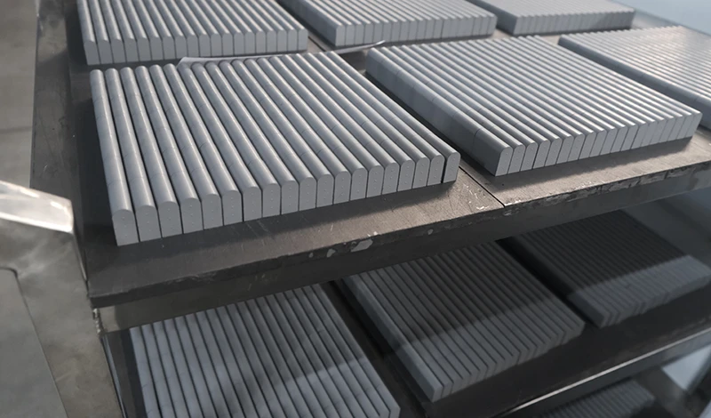
The usual explanation for segmentation is handling: shorter pieces are easier to ship, to lift and to store. That is true, and it is the least interesting part of the design. On edges that work hardpack and refreeze cycles, the reason the joint matters is thermal and mechanical — the edge is cut into segments so that heat and load have somewhere to go, and the service life of the whole assembly is decided at those joints rather than at the cutting line.
This piece treats the segmented blade with thermal protection as a joint problem rather than a shipping convenience, works through the mechanism, and ends with the two procedures that matter in a workshop: replacing one segment, and inspecting the joints.
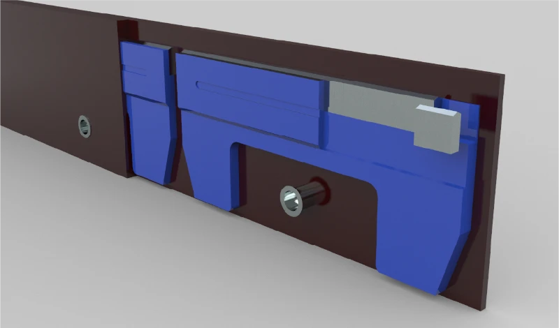
Why blades are segmented in the first place
Because a continuous edge has nowhere to put that movement.
Cutting an edge into segments gives it joints that can accommodate expansion, distribute contact load and localise damage, which is why segmented designs dominate where surfaces are uneven and temperatures swing.
Three forces act on a long edge at once. Thermal expansion and contraction change its length between a cold morning and a shift that ends with the steel warm from friction. Contact load varies along the length as the surface changes under the blade, so a continuous edge has to span from a point carrying full pressure to a point carrying none, and it does that by flexing. And impact arrives at one point rather than along the whole edge, so a continuous edge transmits the resulting stress into material metres away from the event.
Segmenting changes all three. Each segment is short enough that the expansion it has to accommodate is small, stiff enough to stay flat over its own length, and isolated enough that an impact’s consequence is largely contained. The trade is that the assembly now depends on its joints, and a joint is a place where movement can start if it is built wrong. The construction of the segmented and rubber-flex range is set out on the carbide blade page.
Joint geometry and load transfer
Load moves through a joint in two ways, and the design decides which one dominates.
A butted joint transfers load through the faces of the adjoining segments, so the flatness of those faces and the condition of the material beneath them set how evenly the load is shared. A lapped or overlapped joint transfers load through the overlap, which tolerates a less perfect face but introduces a step that the road surface can catch. Either way, the joint is a load path that the continuous edge did not have, and the wear and movement that follow are concentrated there.
The practical consequence is that a damaged joint does not stay local. Once the faces stop mating, the load that should be shared is taken by the fixings alone, and those fixings then work loose in the way described in the component map of the blade system. That is why joint condition belongs in the routine inspection rather than in the end-of-season rebuild.
Thermal expansion and contraction in service
Thermal movement in a plow edge is small in absolute terms and significant in its effect, because it acts on a joint that is also carrying load. Steel’s expansion per degree is modest, but the temperature range an edge sees between a cold start and a warm shift is large, and the resulting change in length is concentrated at the ends of each segment where the joints sit.
Where a joint is designed to accommodate that movement, the segments slide by a fraction and no load accumulates. Where it is clamped without allowance, the movement becomes stress against the fixings, and the evidence appears as fretting marks, polished faces at the joint, or elongated holes. The design intent of thermal protection is to keep that movement controlled rather than to eliminate it; a joint that appears to have moved a little is working as designed, while one that has opened a visible gap is not.
Fastener layout at segment joints
The fastener pattern around a joint is set by the load it has to carry and by the need to keep the joint faces closed. The first fixing either side of a joint carries more of the load than fixings further along the segment, so the layout is usually denser or heavier at the joints than in the middle of a segment.
The consequence for a fleet is that the fixings at the joints wear and loosen earlier than the rest, and that replacing them requires the matching hardware rather than whatever is in the bin. Torque values belong to the bolt diameter, grade and seat rather than to the position, but the check interval at the joints can legitimately be shorter than elsewhere on the edge. Where a fleet is standardising hardware across a mixed fleet, the joint fixings are the ones that must not be substituted.
Replacing a segment instead of a full edge
Replacing one segment is the advantage the design exists for, and the procedure is short enough to follow at the roadside. The steps below are ordered so that the joint condition of the neighbouring segments is checked while the edge is open.
- Inspect the mounting line and the faces of the segments that will stay in place before removing the damaged one.
- Remove the fixings at both joints of the damaged segment, keeping them with the segment so the hardware stack is not mixed.
- Clean the faces on the segments that remain; contamination under a joint is what lets it move.
- Fit the replacement, checking that its faces mate with the neighbours rather than sitting proud.
- Torque to the value specified for the fixing, working from the joints inward.
- Re-torque after the first shift, as the joint settles.
The step that is omitted most often is the first one, and it is the one that decides whether the replacement lasts. A new segment fitted between two damaged faces reproduces the failure it was meant to fix.
Inspection points at joints
Joint inspection is a short procedure that checks five things, and it is worth doing at every edge inspection rather than only at the end of the season. The checks follow the failure sequence described above, from the first visible sign to the condition that takes the edge out of service.
- Look for a visible gap between segments, which indicates the faces are no longer mating.
- Check for fretting polish or rust staining at the joint, the trace that movement has started.
- Check the fixings either side of the joint for torque loss before checking the rest of the edge.
- Check the material under the joint for deformation or cracking.
- Check the neighbouring segments for local damage, since impact rarely stops at one segment.
A joint that passes all five is left alone, and the time saved by not inspecting the rest of the edge as often can be spent on the routes that produce the damage. Material and hardness test methods that support a specification for these components are published by ASTM International and ISO.
Segment systems versus one-piece edges
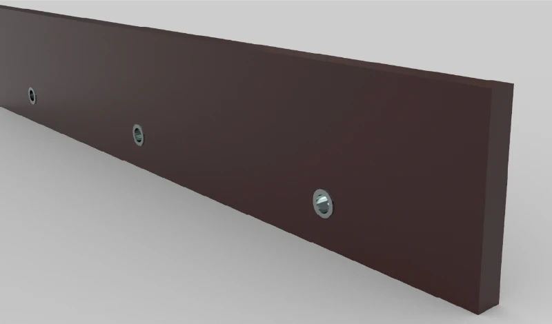
The comparison between a segmented assembly and a one-piece edge is not a straight contest, because the two are optimised for different conditions. A one-piece edge is stiffer and has fewer places for movement to begin; a segmented edge manages thermal and load variation better and allows partial replacement.
The variables that separate them are the surface the edge works, the temperature range it experiences, and the value of replacing a section rather than a whole. On a smooth, stable route with modest temperature movement, the one-piece edge’s simplicity is real. On routes where the surface changes under the blade and the edge sees hardpack, refreeze and wide temperature swings, the joints are doing work that a continuous edge would do by flexing along its whole length — and the replacement economy is a second benefit rather than the main one. The wider material comparison is covered in the steel, carbide and clad options on the snow plow blade hub.
Choosing segment length for a moldboard width
Segment length is a compromise between joint count and handling weight, and the compromise lands differently on a narrow blade than on a wide one. Shorter segments mean more joints to maintain and more fixings to check; longer segments mean fewer joints but heavier pieces to lift and a larger single item to replace when one section is damaged.
The rule that keeps it practical is to cover the moldboard with the smallest number of segments that still allows one person to handle a replacement. A blade that needs three people to change a segment will not get its segment changed during the season, whatever the theoretical advantages of the layout. On wide municipal moldboards that usually means a mix of lengths rather than a single repeated size, with the end segments sized to close the remaining width cleanly.
Two further checks belong in the choice. The end segments should not be so short that their fixings sit close to the moldboard edge, because that is where distortion starts. And the segment boundaries should sit away from the parts of the route that produce the most impact, so a strike damages material inside a segment rather than at a joint.
How joints behave on unsealed and broken surfaces
The behaviour that makes segmented edges attractive on paved routes changes character on unsealed and broken surfaces, and the difference is worth understanding before fitting them there. On gravel the blade is not cutting a bonded layer; it is following a surface that moves, and the joints become the place where the assembly absorbs that movement.
Two effects appear. The segments conform individually, which reduces the load transferred into the moldboard when a stone passes under one of them. And the joints accumulate grit, which is abrasive against the mating faces and the fixings. The practical consequence is that a segmented edge used on unsealed surfaces needs its joints cleaned and checked more often than the same edge on pavement, not because the design is weaker but because the environment works on the parts a continuous edge does not have.
Setting up a new segmented edge: the fitting order that keeps joints closed
The order in which a segmented edge is fitted decides whether the joints close properly, and fitting from one end as though it were a single piece leaves the last joint open. The sequence below starts at the centre and works outward, which pulls the assembly together rather than pushing gaps towards one end.
- Clean the moldboard mounting line and check it with a straight edge before anything is fitted.
- Position the centre segment and bring its fixings up finger-tight.
- Add the next segment outwards, checking that its face mates with the previous one before tightening.
- Work outwards to both ends, alternating sides, keeping the joints closed as you go.
- Torque the whole row once every segment is positioned, then re-check the joints after the first shift.
The check that catches most fitting errors is step three: a segment that needs force to bring its face against its neighbour is telling you the mounting line is not flat, and tightening it anyway leaves a joint under permanent stress.
Winter maintenance research on edge behaviour is published by the Transportation Research Board, road maintenance guidance by the Federal Highway Administration, component and mounting practice by AASHTO, and equipment guidance by the Association of Equipment Manufacturers.
SENTHAI manufactures segmented rubber-flex blades and carbide edges in Rayong, Thailand, with the joint hardware specified for the pattern and the segment length matched to the moldboard width. Fitment is confirmed against the customer’s measurements before production.
FAQ
Are segmented blades better than one-piece edges?
Better at managing load and heat and at replacing damage in sections. Worse at rigidity, because every joint is a place where movement can start.
What does thermal protection mean on a plow edge?
It means the joint is designed to accommodate expansion and contraction rather than being clamped solid. The segments can move relative to each other without opening a gap.
Why do segment joints loosen?
Usually because the joint was assembled without the settling re-torque, or because the face under the segment is not flat. Movement then opens the gap further with each pass.
Can I replace one segment and keep the rest?
Yes, and that is the main advantage of the design. Check the faces of the neighbouring segments while the edge is open, because damage rarely stops exactly at a joint.
How often should segment joints be inspected?
At every edge inspection and after any impact. The joints are the first place a problem appears, so checking them costs less than checking the whole edge more often.
Send the moldboard width, the segment length you run and the surface the machine works. The SENTHAI engineering desk will confirm the segment layout, the joint hardware and the replacement segment before quoting.
This article is one step in the Snow Plow Blade Selection Guide, which works the whole decision in order — surface, position, size, geometry and material — through to the written specification.