A truck came in for a cutting edge and left needing five items: the edge, two shoes, a set of fixings, a trip spring, and a repair to the moldboard behind the wear plate. None of the five had failed at the same time. They had failed in an order, and the workshop had been replacing each one as it appeared rather than reading the sequence.
The components of a snowplow blade system wear on their own schedules, and the value of treating them as a system is that the order of failure tells you what is coming next. What follows gives each assembly the same three questions — what to inspect, what proves it is sound, and what failure looks like — then puts them back in the order they usually fail.
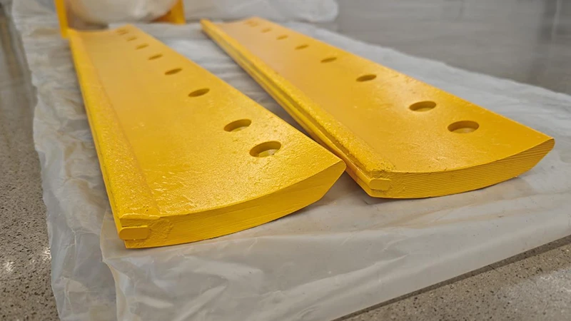
Cutting edge, wear plate and shoe assembly
The front of the system is three parts, not one consumable.
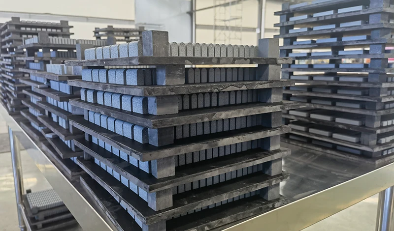
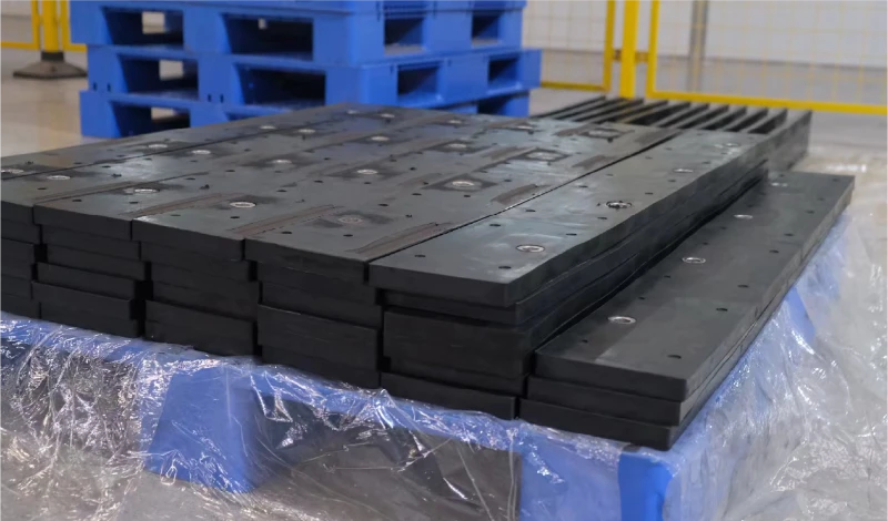
The cutting edge wears by design and is meant to be replaced; the wear plate protects the moldboard behind it; and the shoes set how much of the edge reaches the surface.
Inspect the edge by measuring remaining material at fixed positions rather than by looking at it, and measure the plate and shoes at the same time so the three intervals can be compared. What proves the assembly sound is a set of measurements that match the figures taken when the parts were fitted. What failure looks like is a wear pattern rather than a worn part, and the pattern names the fault.
- Inspect: remaining material at marked positions, shoe height on both sides, plate thickness.
- Proves sound: readings matching the fitting baseline, with shoes equal and plate above its limit.
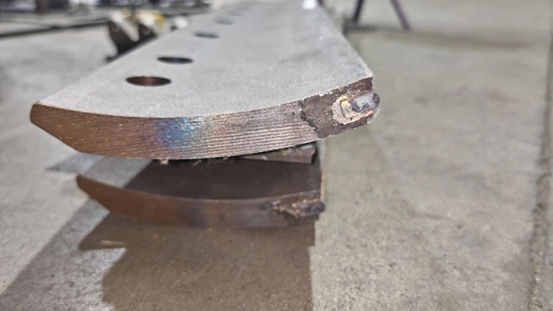
- Failure looks like: an edge worn at one end, shoes worn twice as far on one side, or a plate through while the edge still has material.
Those patterns say the blade is not sitting level or the setting is wrong, and replacing the three parts without correcting it reproduces the same wear. The intervals and thresholds are set out in plow blade wear plates.
Fasteners, nuts and torque interfaces
The fixings are the cheapest parts on the machine and the ones whose failure causes the largest consequences, because a fixing that loosens lets an edge move and the movement damages everything it touches.
Inspect the fixings by checking torque at a sample of positions rather than at one, and by looking for the traces that movement leaves. What proves them sound is a torque reading at the specified value on clean hardware. What failure looks like is a fixing that will not hold its value.
- Inspect: torque at several positions, head seating, washer condition, fretting polish on the edge face.
- Proves sound: specified torque on clean hardware, seating faces intact, no elongated holes.
- Failure looks like: a fixing that will not hold torque twice, which means the joint has been moving for some time.
At that point the diagnosis has moved from the hardware to the mounting. The torque values and the settling check belong together, and both are covered in blade hardware, torque and wear plates.
Moldboard and trip mechanism
The moldboard and the trip mechanism are the parts a fleet inspects least and pays for most, because both fail slowly and are hidden behind the parts that wear quickly.
Inspect the moldboard along the mounting line with a straight edge and check for cracking around the hole row, and check the trip mechanism by releasing it under load rather than by hand. What proves it sound is a mounting line that a straight edge sits flat against, a trip that releases and resets through its full travel, and springs that have not taken a permanent set. What failure looks like is an edge that will not sit flat, a trip that does not reset after a strike, or a spring that has lost its length. Any of those takes priority over a worn edge, because fitting a new edge onto a distorted line starts the next edge’s life with a fault already in it.
Hydraulic and electrical attachments
The attachments are the part of the system that the operator notices first and the maintenance record mentions least, because their failures look like operating faults rather than equipment faults.
Inspect the hydraulic circuit for leaks at the ram and fittings, the electrical connections for corrosion at the plugs, and the control interface for response rather than function. What proves them sound is a blade that holds an angle under load, a ram that does not creep, and controls that respond without delay at low temperature. What failure looks like is a blade that drifts off its angle, a function that works when warm and not when cold, or intermittent control response. Those symptoms are usually found in the connectors and the fluid rather than in the electronics, and they are worth chasing before the storm sequence rather than during it.
Operator-facing settings and adjustments
The last assembly is not a part at all, and it is the one that decides how long the other four last. Blade angle, down-pressure, shoe height and working speed are settings, and each one moves the load the edge and the moldboard have to carry.
Inspect them by checking the machine against its own recorded baseline rather than against a specification sheet, and confirm that the settings recorded at the last changeover are still in place.
- Inspect: blade angle, down-pressure, shoe height and the working speed the operators actually use.
- Proves sound: values matching the changeover record, producing a continuous cut line without stalling.
- Failure looks like: settings that have drifted upward over the season, which is the usual response to an edge that has stopped cutting.
The drift is self-reinforcing: extra down-pressure or a steeper angle is added to make a worn edge cut, and it accelerates the wear that caused the problem.
Failure order on typical fleets
The order is consistent enough to plan against, and the parameter behind it is load per unit of contact rather than part price. The edge takes the highest contact load and is designed to wear out; the fixings and shoes take the load that the edge passes back and fail by loosening and abrasion; the trip and moldboard take the residue, which is why they last longest and cost most to repair.
| Assembly | What drives failure | What it damages next | Typical check |
|---|---|---|---|
| Cutting edge | Contact load and abrasion | Fixings, then the mounting line | Every edge inspection |
| Fixings | Torque loss and movement | Hole elongation, then the moldboard | After the first shift and each storm sequence |
| Shoes | Abrasion on the running face | The edge, through a change in setting | With every edge check |
| Moldboard and trip | Impact energy and accumulated distortion | The next edge fitted to it | Pre-season and after any strike |
| Hydraulics and controls | Corrosion, cold, wear in the circuit | Operating consistency, then the edge load | Pre-season and mid-season |
Reading the table down the second column gives the maintenance logic: only the edge is designed to fail. Everything below it is failing in response, and a fleet that replaces the edge without checking what it damaged keeps paying for the same event.
Spares list by part, not by kit
The spares decision follows the failure order rather than the catalogue. A fleet that holds one edge per machine and no fixings will still lose the machine on the day a fixing lets go, because the replacement edge is useless with the hardware it was supplied with already in service.
The list that works has four lines: a full fixing set per machine plus spares, shoes for the machines that run them, the trip and spring parts that cannot be bought locally during the season, and the edge itself. Grouping them by assembly rather than by a generic kit makes the store checkable against the table above, and the full range of edges and hardware is on the snow plow blade hub.
Pre-season checks and shift checks are not the same list
The five assemblies need checking on two different rhythms, and running one list for both is why fleets either over-inspect or miss the failures that matter. A pre-season check can take an hour per machine and look at everything; a shift check has to be finishable before the operator leaves the yard.
- Pre-season: mounting line straightness, moldboard and trip function, hydraulic and electrical condition, settings recorded to a baseline.
- Shift check: edge material visible and attached, fixings present and seated, shoes intact, no new noise or vibration reported.
- Never on a shift check: torque verification of the whole row, which belongs to the scheduled service rather than to the start of a storm.
The distinction matters because a shift check that takes too long stops being done, and a pre-season check that is skipped leaves the fleet discovering the trip mechanism mid-season. The weather guidance published by the Federal Highway Administration treats pre-season preparation as a scheduled activity for exactly that reason.
Recording what you find so the next check is faster
A checklist that leaves no record has to start from scratch every time. The record that pays for itself is short: the machine, the date, the readings at the marked positions, and the action taken where an assembly failed a check.
Two habits turn that record into something a fleet can use. The first is measuring at the same positions each time, so two readings produce a rate rather than two impressions. The second is recording the reason for each replacement — wear, impact, or found loose — because the reasons separate normal consumption from the failures the other four assemblies cause. After one season, that record tells the fleet which assembly is genuinely the first to fail on each route, which is the number the spares list should be built on rather than the catalogue order.
Winter maintenance research on equipment and operations is published by the Transportation Research Board, road maintenance guidance by the Federal Highway Administration, mounting and component practice by AASHTO, equipment guidance by the Association of Equipment Manufacturers, and operator experience by the Snow and Ice Management Association.
SENTHAI manufactures carbide snow plow blades, rubber-flex blades and cutting edges in Rayong, Thailand, and supplies the hardware and wear parts that belong with them. Fitment is confirmed against the customer’s mounting measurements before production.
FAQ
What are the parts of a snowplow blade system called?
The cutting edge is the wearing part along the bottom, the moldboard is the curved face behind it, the trip mechanism lets the blade fold back on impact, the shoes or skids set the cutting height, and the mounting and hydraulics carry the whole assembly on the vehicle.
Which part of a plow blade system fails first?
The cutting edge wears first and is designed to. Fixings at the joints and the shoes usually fail next, and the moldboard behind the wear plate is the part that fails last and costs most when it does.
Should a snow plow blade touch the ground?
The cutting edge should reach the surface and the moldboard body should not. Where the body is in contact, the edge is worn past its limit or the blade is set too steeply, and both accelerate damage further back in the assembly.
What is the optimal cutting edge angle for a snowplow blade?
There is no single angle: it is the setting that produces a continuous cut line without stalling the machine on that route. Record it once per machine and treat it as a fixed value until the route changes.
How often should the whole blade system be inspected?
Four times a season covers most fleets: once before the season, once at the mid-point, once at the end, and after any strike that bent or moved the blade. The edge and fixings are checked more often than that, as part of the routine around each change.
Send the machine, the assemblies it runs and the order in which parts have been failing. The SENTHAI engineering desk will confirm the edge, the hardware and the wear parts against the measured mounting pattern.