A fleet that had been replacing a full set of inserts every January found one edge in March with three inserts missing and the rest barely worn. The edge had been run over a section of road where a utility trench had settled, and the impact load had been concentrated at four positions for the whole season without anyone looking at the row. The parts cost less than the two days of route cover lost while the blade came off.
Wear patterns are the cheapest diagnostic a fleet has, and they are usually read as pass or fail rather than as evidence. This guide covers what normal progression looks like, how chipping and pull-out differ, why one blade wears unevenly across its width, how to tell road wear from debris damage, and the routine that turns an inspection into a specification change.
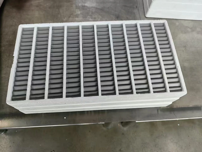
What a worn insert is actually telling you
An insert that has come off a machine carries three pieces of information, and only one of them is about the insert. The first is how much material has gone, which sets the service interval. The second is where on the insert it went, which identifies the mechanism. The third is where in the row it happened, which identifies whether the cause is the surface or the machine.
Reading all three together is what separates a specification that improves from a specification that merely changes. A fleet that only records height lost can see that an edge wore, but not that it wore at the ends, or that the inserts near a segment joint were the first to go. Those are the observations that lead somewhere.
It is worth measuring before cleaning as well as after. Grit packed around a joint or against a pocket wall is itself evidence of where material is collecting, and it is the kind of detail that disappears the moment the edge is washed.
Carbide insert wear patterns: flank wear and normal progression
Flank wear is normal; everything else is a message.
Normal progression is an even loss of material across the working face of every insert in the row, with the contact face staying flat or wearing into a shallow, regular profile. Nothing chips, nothing discolours, and the wear rate across the row varies little between positions.
When that is what comes back, the specification is working and the only useful action is to record the rate so the replacement interval can be planned from data.
The rate matters more than the total. A fleet that knows its edges lose a measurable amount of insert height per hundred hours of route work can plan a change-out around the weather rather than in the middle of it, which is the difference between a scheduled workshop visit and a stopped truck. Maintaining a service record of that kind is described in the practice published by the Snow and Ice Management Association.
Chipping and microfracture
Chipping is a load signature, not a wear signature, and it appears differently depending on whether the load was a single event or a repeated one. A single heavy impact usually removes a corner or a section of the contact face and leaves a clean fracture surface. Repeated smaller overloads produce a network of small cracks and spalled areas along the contact edge.
Where the chips are concentrated at the ends of the edge, the cause is usually the shoulder of the road, a driveway entrance or a transition between surfaces. Where they are spread along the row, either the grade is too hard for the impact the route delivers or the edge is running with more down pressure than the design intended. Both cases lead to a specification change, but to a different one: the first is about geometry and fitment, the second about grade.
Pull-out and retention loss
An insert that has left its position is a different failure entirely, and the evidence it leaves behind is what identifies the cause. Where the filler metal is still bonded to the steel and the insert has gone, the joint moved before it failed, or it was never seated flat. Where the pocket is fretted and polished but the fixing is still in place, the insert has been moving under load for some time before it was lost.
The distinction decides who can fix it. A pattern of pull-outs across several edges from different batches points to a joint problem; a pull-out in one position on one edge points to a fitment or impact problem at that position. The underlying causes and the prevention measures are set out on the insert loss page.
Uneven wear across a blade
A pattern that changes along the working width is almost never a material problem, and treating it as one wastes the season it took to produce the evidence. Four causes account for most of it.
- A mounting line that is no longer straight, which changes contact pressure along the width.
- Down pressure that is not distributed evenly by the machine’s own geometry.
- Inserts at different heights in the same row, usually after a partial replacement.
- A section of the edge where the pitch is tighter than the rest, concentrating load at that point.
The fourth cause is the one that repeats. Where spacing varies to avoid a bolt position, the tight section wears first every season, and the pattern is then read as a grade problem. What the pitch is doing along the edge is examined on the spacing and density page.
Wear from road surface versus debris
The road produces smooth wear and debris produces irregular damage, and the two are usually distinguishable at a glance once the difference is known. Surface wear follows the contact face and shortens the insert evenly, because the abrasive is fine and distributed. Debris damage is localised: a gouge across a face, a nick at an edge, or a chip that starts at a point rather than along a line.
Where both signatures appear in the same row, the edge is working a mixed route rather than a single surface, and the specification should be built for the worst section rather than the average one. The other thing worth noting is timing: surface wear accumulates steadily, while debris damage tends to appear suddenly, which is why an inspection that finds irregular damage is often the first sign that something changed on the route.
Three wear myths that cost fleets money
Three beliefs about insert wear are repeated often enough to change purchasing decisions, and each one leads a fleet away from the observation that would have helped.
- That a shorter insert has been abused. Length alone says nothing: a shortened insert with a smooth contact face has been abraded normally, and the useful question is the rate.
- That a chipped insert proves the grade was too hard. It may prove that, or it may prove the edge met something it should not have, or that the insert was never seated properly.
- That inserts of the same grade wear the same everywhere. The same grade on two routes with different surfaces and different down pressures will not produce the same pattern, which is why specifications belong to routes rather than to fleets.
The material behaviour behind those beliefs is documented through the test methods published by ASTM International, and the terminology used to describe a fractured or worn insert comes from the same family of standards. Using that vocabulary in a supplier conversation usually shortens it considerably.
Photographing wear for supplier review
A photograph answers questions that a description cannot, and the sequence below produces images a supplier can actually read. It takes less time than writing a paragraph about each insert.
- Photograph the whole edge from directly above, so the wear distribution along the width is visible.
- Photograph the end view, which shows insert height, contact profile and any pocket movement.
- Photograph the worst three inserts individually, with a scale or a coin for size reference.
- Photograph the base of any insert that has come out, which shows whether filler metal stayed with the steel.
- Note the machine, the route and the hours run alongside the images.
The fourth image is the one that most often resolves a disputed claim, because it shows directly whether the joint or the insert was the weak point. Photographing the same positions again after the next season gives a comparison that no description can match.
Trigger points for replacement
Replacing on a fixed calendar ignores the evidence the edge is producing, and replacing on appearance alone is inconsistent between workshops. Four trigger points cover most fleets, and each can be written into an inspection sheet.
The first is remaining insert height against the minimum the design allows, which is a measurement rather than a judgement. The second is loss of cutting performance on the material the edge is meant to clear, particularly a bullnose profile that has flattened at the crown. The third is any insert that has moved in its position, since movement is a leading indicator of loss rather than a cosmetic issue. The fourth is a change in the wear pattern itself, which indicates that the route or the machine has changed even when the wear rate has not.
Recording wear so the next order is better
The value of an inspection is realised in the next purchase, and that requires the observation to survive the season. Recording insert height at removal, the positions that wore first, and a photograph of the row from each edge gives the next specification something to be argued from rather than remembered.
Where a fleet keeps the record against the route rather than the machine, comparisons start to mean something: two edges on the same route can be compared directly, and a change in grade or pitch can be tested rather than assumed. The decision that follows from a pattern of even wear is set out on the replace inserts or whole edge page.
SENTHAI manufactures tungsten carbide inserts and carbide plow edges in Rayong, Thailand, with grades and patterns confirmed against the wear evidence a fleet records rather than against a catalogue designation. Batch-level records are described on the quality control page, and brazing practice for the joints behind these inserts is published by the American Welding Society. Research on winter maintenance performance across a network is published by the Transportation Research Board, and the classification conventions for hardmetals by ISO.
FAQ
What does even wear along an insert row mean?
It means the specification and the route agree. Even loss of material across the working face of every insert is the intended outcome, and it should be recorded rather than corrected. The one action worth taking is to note the wear rate, so the next season’s replacement interval can be planned from a number.
Is a chipped insert a warranty claim?
Usually not on its own, because chipping is a load signature rather than a material defect. One chipped insert among sound neighbours points to an impact or a fitment issue; a whole row chipping points to a grade or duty mismatch. A claim is stronger when several inserts from the same lot fail the same way at the same place.
How do I tell wear from the road apart from wear from debris?
Road wear is uniform and follows the contact face, producing a smooth shortened insert. Debris damage is irregular: gouges, nicks and chipped edges concentrated in the middle of a face rather than along the contact line. Where both appear in the same row, the edge works a mixed surface rather than a single one.
How often should inserts be inspected?
At every blade change and once mid-season as a minimum, because the patterns that matter develop gradually and are easier to read against a previous measurement than from a single look. Inspections that are only done when something feels wrong always happen too late to change the specification for the following season.
Send the wear measurements, the position of the worst inserts along the edge and photographs of the row. The SENTHAI engineering desk will read the pattern and confirm whether the cause sits in the grade, the geometry or the fitment.
This article is one step in the Carbide Insert Selection and Replacement Guide, which covers grade, geometry, spacing, fitment tolerance and the replace-or-re-plate call.