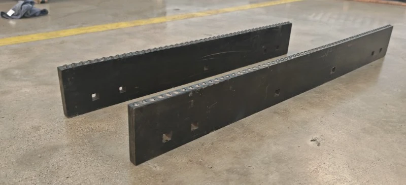
A fleet orders a packed ice kit from a description of the machine and a photograph of the old edge. The kit arrives, the blade comes off the truck, and the mounting pattern is one hole out across part of the width. Nothing is wrong with the kit as made, and the machine is out of service for three days while a second one is produced against measurements nobody took.
This is the sequence that prevents that outcome. It sets out the measurements to take before an order is placed, the fitment conditions that decide whether the arrangement will perform on the carrier, what a quotation needs in order to be a specification rather than an estimate, and what to check when the kit arrives.
What goes wrong when a kit is ordered from a description
Orders go wrong in three recognisable ways, and all three trace back to a measurement that was assumed rather than taken. The pattern is one: a fixing layout that is close but not identical across the width, which fits at one end and not the other. The count is the second: an insert arrangement based on the working width alone, which ignores the pitch and produces the wrong contact density for the surface.
The third is the carrier. A kit that is dimensionally correct can still fail to perform if the machine cannot hold down pressure, and that condition is not visible in any measurement of the blade. It is a property of the machine, and it has to be established before the order rather than discovered in service.
The cost of each failure is similar: the edge is made to a specification that did not include the one input that mattered, and the machine is out of service while the correction is produced.
Packed ice kit ordering: the measurements to take first
Measure the machine, not the part being replaced.
Five measurements define a packed ice kit. The working width and the blade height set the size and the arrangement. The bolt pattern, with hole diameter and centre-to-centre spacing, sets the mounting.
The carrier class and its down-pressure capability decide whether the arrangement will cut, and the clearance above and behind the edge sets how much material the kit can add without fouling the frame. A sixth input, the surface the route produces, chooses the pitch and the grade.
Taking all six takes an hour with the machine available and settled. Taking five of them takes the same hour and produces an order that has to be remade, which is why the carrier check is written into the sequence rather than left to a conversation. How the pattern itself is verified is set out on the bolt pattern verification page.
Blade and carrier measurements
The dimensional inputs are straightforward and are usually taken from the machine with the blade in place, which is the condition the kit has to fit. Working width is measured along the full cutting line rather than between the mounting points, since the arrangement has to cover the width the blade works rather than the width of the frame.
Blade height is measured from the mounting line to the current cutting edge, and it matters because it sets how much insert height can be presented without exceeding the machine’s adjustment range. Where a fleet is replacing a worn edge with a kit that carries taller inserts, the available adjustment is worth measuring explicitly: a specification that performs well on paper and cannot be set up on the truck is not a fitment.
Bolt pattern and hardware
The pattern is the input that produces the most failed orders, and it needs more than a centre-to-centre figure.
- Hole diameter, since the kit has to accept the hardware the fleet already uses.
- Centre-to-centre spacing, measured between adjacent holes and recorded across the full width rather than at one point.
- Countersink or counterbore form, where the fixings are recessed into the edge.
- Any irregular spacing, since a pattern that is not uniform has to be recorded as a layout rather than as a pitch.
The fourth item is what distinguishes a pattern drawing from a pattern description. Where the spacing varies to clear a frame member or a rib, the order has to carry the layout, and a single pitch figure will produce an edge that fits in the workshop and not on the machine.
Insert count and configuration
The insert count follows from the pitch, and the pitch follows from the surface rather than from the width. Two edges of the same working width can legitimately carry different numbers of inserts, and the difference sets both the cost and the contact pressure at each point.
For an order, the count should be stated as an arrangement rather than a total: how many positions across the working width, at what spacing, with what insert profile and dimensions. Stating a total alone leaves the layout to be decided by whoever builds the edge, which is how two kits ordered to the same description arrive with different arrangements.
Down-pressure capability check
The capability check has two parts and is often confused with the first one alone. The first is whether the carrier can apply down pressure at all, which is a machine specification. The second is whether that pressure is adjustable and can be held consistently, which is a machine behaviour.
Both matter. A carrier with enough force but no control applies the same load to a soft surface and a bonded one, which either damages what it should protect or fails to cut what it should reach. Establishing the answer takes a few minutes with the machine and the operator, and it is the single input that most often decides whether a kit should be ordered at all. Why the arrangement depends on it is described on the packed ice kit page.
Mounting and clearance limits
The kit adds material below and in front of the mounting line, and there has to be room for it. The table below sets out what to measure and what each limit affects.
| Measurement | What it constrains |
|---|---|
| Adjustment range above the current cutting line | How much insert height can be presented before the blade runs out of adjustment |
| Clearance behind the edge to the frame or moldboard | Whether the body can sit without fouling at full angle |
| Gap to any trip mechanism or spring | Whether the edge can deflect without contact |
| Swept envelope at full articulation or wing deployment | Whether the kit fouls the carrier at the extremes of movement |
The fourth row is the one that gets missed, because it is measured in a position the machine is rarely left in. Checking full articulation before ordering takes a few minutes and prevents a kit that works on a straight pass and interferes at the end of a run.
Quote information to provide
A quotation becomes a specification when the enquiry carries the inputs below, and it stays an estimate when any of them is a description.
- The five dimensional and clearance measurements, with the method used to take each one.
- The bolt pattern as a layout, including hole diameter and any irregular spacing.
- The carrier class and its down-pressure capability, stated as adjustable or fixed.
- The surface and route conditions the arrangement is being chosen for.
- The documentation required with the lot, and the batch reference format the fleet records.
The fifth item is easy to overlook and it is what makes a later comparison possible. A fleet that receives its lots with a reference fixed to the same format can compare two seasons and two suppliers; one that receives them without cannot.
Installation support options
Installation on an isolated edge is not complex, but it has two requirements that differ from fitting a conventional blade: the inserts have to be kept at a consistent height along the width, and the mounting has to be torqued and checked in a sequence that does not pull the body out of line.
What a supplier can provide varies, and it is worth asking for explicitly. A fitting sequence, a specification for the torque and the check order, and a first-fit inspection that confirms the cutting line are the three that matter most, because they are the ones a fleet cannot reconstruct from a drawing.
Checking the delivery against the order
The receiving check is short and belongs before the blade is stripped from the machine.
- Confirm the batch reference and the drawing revision against the order.
- Check the mounting pattern against the layout supplied, on a flat surface rather than by eye.
- Count the insert positions and confirm the profile and dimensions.
- Confirm the fixing hardware is present and matches the pattern.
- Record the receipt against the blade’s record before fitting starts.
The second step is the one that catches the failure this article opened with, and on a delivered edge it takes minutes rather than days. The receiving checks used for loose inserts are set out on the delivery inspection page.
First-fit checks after mounting
After fitting and before the first route, three checks confirm that the kit is presenting what it was specified to present. The cutting line should be straight along the working width when the blade is set at its operating angle. The insert heights should be within the tolerance the drawing allows, checked at several positions rather than at one. And the blade should reach its full range of movement without contact between the kit and the frame.
Those three checks take less time than a route, and they separate a fitment problem from a specification problem while the machine is still in the yard. Where the cutting line is not straight after fitting, adjusting the blade will not correct it.
Common ordering mistakes
The mistakes below account for most reworks on these orders, and each one is a measurement that was assumed.
- Ordering from the working width alone, without the pitch or the insert count.
- Recording a single centre-to-centre figure for a pattern that varies along the width.
- Skipping the carrier check because the kit fits the machine.
- Measuring clearance with the blade in its working position only, and not at full articulation.
The third entry is the most expensive because it is not detectable at fitting. A kit on a carrier without controllable down pressure will fit, run and fail to cut, and by the time that is established the order has been judged as unsuitable rather than as mismatched.
SENTHAI manufactures packed ice carbide kits, inserts and cutting edges in Rayong, Thailand, and confirms the arrangement and mounting pattern against the customer’s measured machine before production. Drawing and dimensional conventions are published by ASME and ISO, equipment standards by SAE International and the Association of Equipment Manufacturers, and material test methods by ASTM International. Kits that need their fitment confirmed against a specific machine can be discussed through the contact page.
FAQ
What measurements do I need before ordering a packed ice kit?
The working width and blade height, the bolt pattern with hole diameter and spacing, the carrier class and its down-pressure capability, and the clearance available above and behind the edge. Those five inputs define the arrangement, the insert count and the mounting pattern, and without them a quotation is an estimate.
Does the kit fit any carrier?
The mounting can usually be made to fit, but the cutting action depends on the carrier being able to hold down pressure and a consistent cutting line. A unit that floats its blade will accept the kit and will not produce the cutting the arrangement is designed for, so the carrier check comes before the order rather than after it.
How is the insert count decided?
From the working width and the pitch chosen for the surface, not from the width alone. Two edges of the same width can carry different numbers of inserts, which changes both the cost and the pressure at each contact, so the pitch belongs in the order rather than in the workshop’s judgement at fitting.
What should be checked when the kit arrives?
The pattern against the drawing, the insert count and profile, the fixing hardware, and the batch reference that ties the lot to its record. Checking these before the blade is stripped avoids discovering a mismatch with the machine already out of service.
Send the working width, the bolt pattern layout, the carrier class and the clearance measurements. The SENTHAI engineering desk will confirm the arrangement, the insert count and the mounting pattern before the kit is produced.
This article is one step in the Packed Ice Edge Guide, which explains why a standard edge skates across hardpack and how to set one up so it bites.