A workshop takes delivery of a replacement edge, strips the old one off, and finds that the new one lines up at the first three positions and is a hole out at the fourth. The old edge came off the same machine that morning, so the conclusion is that the new edge is wrong. In most cases the conclusion is mistaken: the frame moved, and the old edge was either reamed to suit it or had been made to the machine’s current shape.
This is a decision path through that situation, and the order matters. It works through what to check first, how to read hole drift and plate deformation, when a correction is acceptable and when it is not, and how to document the outcome so the same problem does not return with the next order.
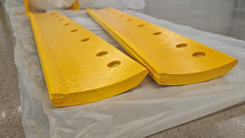
A new edge that will not line up: what to check first
The first check is not the edge. It is the machine the edge is being fitted to, because the frame is the part that has been in service for years and the edge is the part that has just arrived.
Two conditions explain most cases where a replacement will not line up. The mounting line has bowed, usually from an impact at one end, which changes the position of every fixing relative to the others. Or the fixing holes have elongated, which means the pattern no longer locates anything even when the edge matches the drawing exactly. Both are consequences of service rather than of supply, and both are measurable in minutes.
The reason this check comes first is that it is the cheaper of the two errors to find. Where the frame is at fault, the answer is a repair or a decision about the blade; where the edge is at fault, the answer is a return. Getting the order wrong means sending back an edge that was correct and refitting one that will not hold.
Why the moldboard comes before the blade
A plow edge is a consumable bolted to a structure, and the structure is what defines the pattern. Every impact the blade takes is transferred into the frame, so the frame accumulates deformation over a season while the edge accumulates wear. Over several seasons the two diverge, and the divergence is what makes a drawing-correct replacement fail to fit.
That is also why the old edge is not a reliable reference. It may have been reamed during a previous change-out, or made to a pattern taken from the machine after it had already moved. Comparing a new edge against the old one on a bench proves only that they differ, not which of them matches the machine.
Plow blade fitment problems: check the moldboard first
Check the frame before the edge.
Three measurements establish whether the frame is still a valid reference. The straightness of the mounting line along its full length, taken with a straight edge rather than by eye.
The position of each fixing hole relative to the two end holes shows whether the pattern has drifted or elongated locally. The flatness of the face the edge seats against also matters, since a high spot holds the edge off the frame along part of its length and produces a gap that looks like a pattern error.
Where all three are sound, the frame is a valid reference and the edge becomes the suspect. Where any of them is out, the frame has to be corrected before the edge is judged, because there is no way to tell a good edge from a bad one against a moving reference.
Hole pattern drift after impacts
Impact damage shows up in the frame in four recognisable ways, and each points to a different response.
- Elongated holes across several consecutive positions, indicating the edge has been moving and the pattern no longer locates.
- A local spread at one end only, which usually follows an impact against a kerb or a fixed object.
- A bowed mounting line with sound holes, indicating deformation of the structure rather than of the fixings.
- Cracked or torn material between two holes, which is a repair decision rather than a fitment one.
The third entry is the one that is easiest to misread, because the holes look perfect and the edge still will not sit flat. Measuring the mounting line with a straight edge takes a minute and distinguishes it from a pattern problem immediately.
Bent or twisted base plates
A twisted plate is harder to detect than a bent one, because the ends can measure correctly while the middle does not. The test is to check the mounting line at several positions rather than at the ends, and to check it from both sides of the blade where access allows.
Twist matters to fitment because it changes the load path rather than the geometry: an edge bolted to a twisted plate is loaded at two positions and loose at the others, and the fasteners at the loaded positions lose preload first. That pattern of loosening is frequently attributed to the hardware rather than to the frame, which is why the frame check belongs at the start of the diagnosis rather than at the end.
When reaming is acceptable
Reaming is a correction with a narrow acceptable range, and the table below sets out where it applies.
| Situation | Reaming | Reason |
|---|---|---|
| A single hole slightly out of position on an otherwise sound frame | Acceptable within limits | Corrects the misalignment without changing where the edge locates |
| Several holes out in the same direction | Not acceptable | Indicates a pattern problem or frame movement, not a local defect |
| A hole already elongated by service | Not a solution | Enlarging it further removes the bearing face the preload depends on |
| A hole enlarged to accept a wrongly made edge | Never | Converts a supply problem into a permanent frame defect |
The fourth row is the one worth committing to policy. A workshop that reams to make a wrong part fit has no way to recover the frame afterwards, and the next correct edge will not fit either.
When a blade must be remade
A blade has to be remade, rather than corrected, in three conditions. Where the mounting line has moved along its length, because the edge will load unevenly whatever is done to the holes. Where the pattern has drifted so that no consistent layout remains, because any replacement will be made to a shape that does not exist on the machine. And where the frame has been repaired previously in the same area, because the second repair is unlikely to hold and the load path is already compromised.
The decision is worth making early rather than after a second failed fitment. A frame repaired once and re-edged twice costs more than a replacement, and it also consumes the season’s workshop time in the weeks when the fleet can least afford it.
Documenting the issue for the supplier
Where the diagnosis points to the edge, the notification has to carry the measurements that show it.
- Record the frame condition first, so the supplier knows what the edge was offered up to.
- Measure the edge itself against the layout it was ordered to, at the positions where it fails.
- Photograph the gap at the failing position rather than the whole edge, with a rule in the frame.
- State the requirement that was not met, quoting the drawing revision or the purchase order line.
- State how many positions fail and whether the deviation is consistent along the edge.
The fifth item distinguishes the two failure modes a supplier has to act on. A deviation that grows along the edge suggests a pattern error; one that appears at a single position suggests damage or a handling problem. The measurement format used for the original order is described on the blade measurement page.
Preventing repeat occurrences
Three practices stop the same fitment problem coming back next season.
- Measuring the frames at the end of each season, so deformation is found in the workshop rather than during a change-out.
- Keeping a layout per machine rather than per fleet, since frames move individually and a fleet-average pattern hides it.
- Recording every ream or repair against the machine, so a later edge order is not made to a drawing the machine no longer matches.
The third entry is what prevents the situation this article opened with, where an old edge had been reamed and the new one had not. A note against the machine costs nothing and saves a return. Where the frame condition is genuinely marginal, the tolerance that governs the fit is examined on the dimensional tolerance page, and the pattern itself is verified as described on the bolt pattern page.
SENTHAI manufactures plow edges, wear plates and carbide inserts in Rayong, Thailand, and produces edges to a measured pattern with the layout confirmed against the customer’s machine. Drawing conventions for the dimensions involved are published by ASME and ISO, equipment standards by SAE International and the Association of Equipment Manufacturers, and fitment problems that need the frame and the edge assessed together can be raised through the contact page. Research on equipment maintenance practice is published by the Transportation Research Board.
FAQ
Why won’t my new plow edge line up with the bolt holes?
Usually because the frame has moved rather than the edge being wrong. Impacts bow the mounting line and elongate the fixing holes, and a replacement made to the original drawing will then not line up on a machine that has changed shape. Check the frame before questioning the edge.
Is it acceptable to ream out a bolt hole to make an edge fit?
Only where the hole is being corrected rather than enlarged to hide a pattern error, and only by the amount that removes the misalignment without damaging the seating face. Reaming a hole to match a wrongly made edge leaves a joint that will not hold preload.
How can I tell whether the frame or the edge is at fault?
Measure both against the same layout. A frame with a bowed mounting line or elongated holes shows the deviation in the metal rather than in the pattern, while a mis-made edge shows its deviation at the same position on every machine it is offered up to.
Can a bent base plate be straightened?
Some deformation can be corrected and some cannot. A local bend that can be worked back without cracking can be recovered; a mounting line that has moved along its length, or a plate that has been repaired before, will usually load a new edge unevenly whatever is done.
What should I send a supplier when a new edge does not fit?
The measured frame condition, the measured edge, photographs of the gap at the position where it fails, and the machine’s original pattern. Suppliers can act on a measured deviation against a stated requirement; a description of a misfit usually produces a discussion instead.
Send the frame measurements, the edge measurements and a photograph of the gap. The SENTHAI engineering desk will identify whether the frame or the edge is the variable and what the next order should be made to.