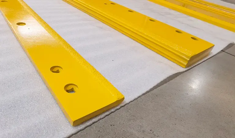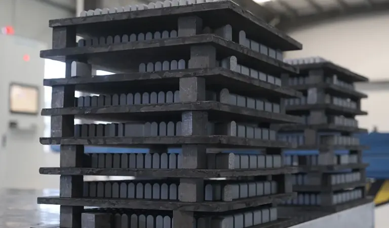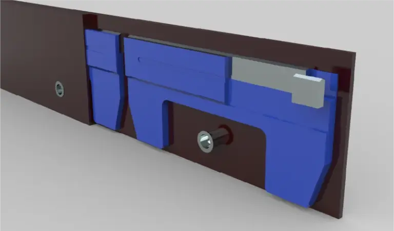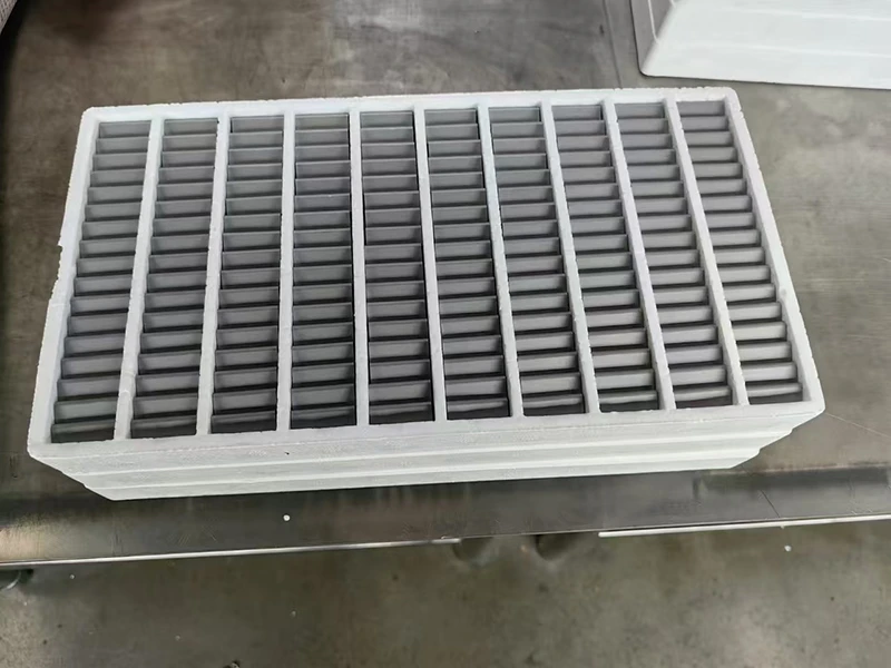
Record its installed condition if that can be done safely, preserve the removal history, and document how the free blade is supported for inspection. Compare like-for-like measurements with the approved geometry. A bowed appearance after removal does not by itself establish when the condition developed or which operation caused it.
Record condition in place if safe and preserve removal history
If removal has not occurred, ask the qualified maintainer whether useful photographs can be taken under the normal safe isolation procedure. Include the attachment, fastener positions and the overall line of the blade. Do not delay necessary safety work for photography. Where no installed-state image exists, explicitly state that the earliest available evidence is after removal.
Record who removed the part, when it was removed and which approved operations were performed. Note handling or support changes that are known, without blaming them for the observed shape. Retain any earlier inspection image that genuinely shows this blade. A picture of another edge from the same order is a product comparison, not this part's history.
The failure-mode guide discusses bending among many conditions. This investigation starts one step earlier: preserving the difference between what was observed in service, during removal and only after the blade was free.
Label free-state orientation and measurement supports
Label face, direction and end orientation before moving the blade again. Have the inspector record the support arrangement used for each measurement, the reference line or plane and the locations inspected. A workshop floor is not automatically a defined measurement surface. State if the part rocks or if a reference is obscured instead of treating the resulting reading as exact.
Photograph the measuring arrangement along with the readings. If a second inspector uses a different orientation or support, retain both methods and results. NIST's metrology guidance is relevant to measurement evidence, but a calibration label cannot make two differently defined measurements describe the same condition. Resolve the method before debating whose number is correct.
Do not straighten, heat or clamp the blade to create a more convenient reference unless that action is specifically authorized as part of the investigation. Such changes can alter the question the retained part is able to answer.
Compare with approved geometry through qualified inspection
Send the controlled drawing and ask which geometric requirement applies in which state. A free component, an assembled component and an installed assembly may be specified or inspected differently; the responsible authority should resolve that distinction for this part. Do not borrow a flatness tolerance from another blade or a generic online example.
Provide the chronology, support photographs and unedited measurements with the review request. If a joining contribution is being considered, CERATIZIT's joining background can help frame specialist questions, but it does not prove that brazing produced the observed bow. Manufacturing, handling and installation records may each remain relevant until examined.
Identify the evidence retained when requesting replacement wear components. Ask for separate written outcomes on conformance, suitability for further service and any proposed corrective work. If the time of deformation remains unknown, preserve that uncertainty rather than giving the replacement order an unsupported causal explanation.
Sources and further reading. The ordered specification and applicable equipment documentation control acceptance and service decisions.
NIST Metrological Traceability: FAQ and Policy ↗CERATIZIT Joining Techniques ↗