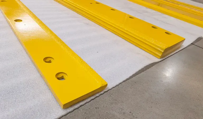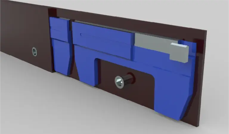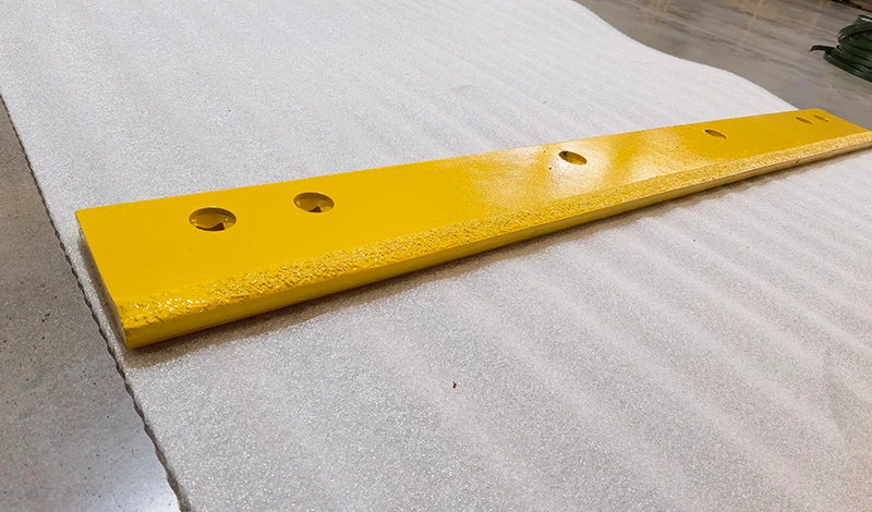
Use a section drawing with thicknesses assigned to named locations. A single nominal thickness cannot define a stepped or varying section, and it may conceal the mounting and clearance features that determine fit.
Use a section view to distinguish body, mounting land and wear section
Choose a section view that cuts through the relevant change in profile and mark its location on the overall blade drawing. Label the mounting land, body and working section according to the actual design. Show which face is the mounting reference. If the section changes along the blade’s length, identify the additional locations rather than implying the first section applies everywhere.
The blade dimension guide supplies the wider measurement context. In this case, a supplier form with one thickness box should be treated as a summary field, not a complete specification. Enter a reference to the controlling section drawing instead of selecting whichever thickness seems most representative.
Specify measuring locations and orientation rather than one nominal thickness
For every reported thickness, state where and in which direction it was measured. Distinguish a design dimension from a remaining dimension on a worn sample. A measurement across a sloping or damaged surface should not silently become the thickness of an intact rectangular section. Keep uncertain transitions marked for review.
The measurement traceability reference is relevant to the measurement basis, but it does not define your blade’s measuring locations. Those must come from the drawing and agreed inspection method. Ask the supplier to return its interpretation in section before manufacturing, especially if its quotation software reduces the part to a rectangular stock size.
Check seating and surrounding clearances using the complete assembly drawing
Compare the proposed profile with the complete assembly: seating surface, cover plate if present, hardware arrangement and surrounding clearance. Use equipment-specific documents where they establish those interfaces. No generic thickness recommendation can replace that comparison. A thicker wearing region does not authorize changing the mounting land or fastening stack.
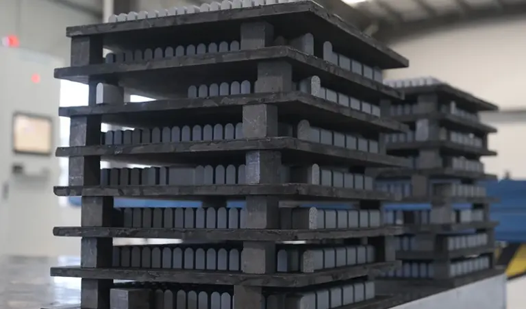
When enquiring about a carbide replacement blade, include the section view with the outer profile and hole pattern. Request an acknowledgement that the quoted part follows that section, rather than merely uses the same maximum thickness. Have receiving inspection check the named locations and the transition features specified on the approved drawing. The useful outcome is a reproducible description: another inspector should know exactly where each value belongs without handling the original sample or relying on a verbal explanation.
Primary references support the specific points linked above; equipment documentation applies to its stated models.
WESTERN official document library ↗NIST Metrological Traceability: FAQ and Policy ↗