Do not trim it as an improvised fitment fix. Stop the installation, identify the contact point and compare the blade, guard and kit configuration. Obtain corrected parts or an authorized disposition before changing the interface.
Stop the fit attempt and document the contact point without modifying the part
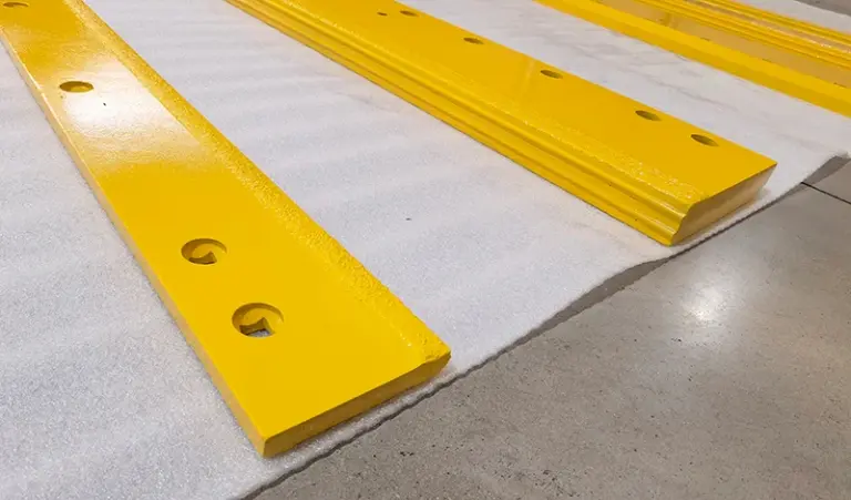
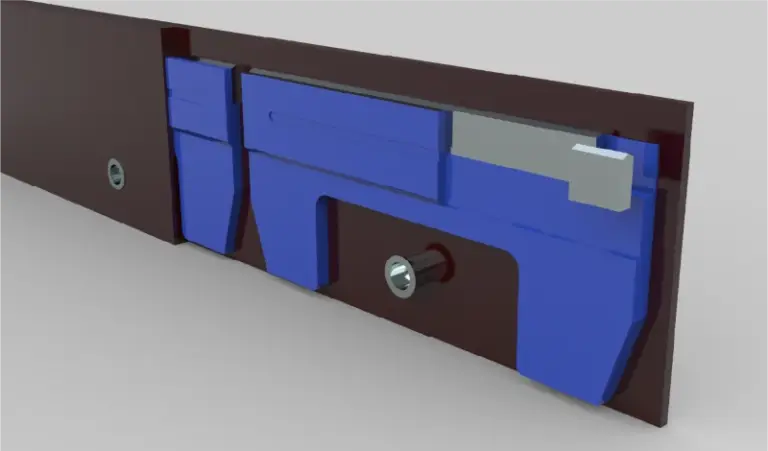
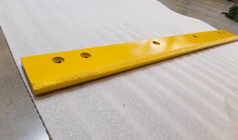
Record where contact occurs using the installed orientation and part identifiers. Show the blade end, guard and intended seating face in the same view if safely possible. State whether the obstruction is visible before fastening or appears during the approved assembly sequence. Do not continue tightening or remove material to see whether the remaining pattern fits.
The fitment troubleshooting guide addresses broader mismatches. This problem is specifically an end-interface conflict, so retain the relevant components together for review. A photograph of the blade alone omits the guard relationship that needs explaining, while a photograph of the contact alone may hide which revision of each component is present.
Compare full replacement-kit contents, guard revision and end dimensions
Compare the actual replacement package with the equipment’s required configuration. The FISHER HC accessory page includes an example where complete edge replacement requires separate curb guards. That is a model-specific example, not a requirement for every plow. Its relevance here is to check kit scope rather than assume that an existing guard must work with every replacement edge.
Ask whether the supplier’s drawing assumes a different guard, end profile or companion assembly. Compare the end-to-hole distance and mounting orientation against the approved references. Also distinguish damage or previous modification from the intended geometry. An interference can have several possible explanations; identifying it is more useful than selecting a trimming amount from a photograph.
Obtain written disposition or corrected parts
Request a written disposition tied to the exact blade and guard combination. It should specify whether the supplied part is incorrect, a companion part is required, or an engineered change is proposed. Any modification needs the responsible authority’s approval and an appropriate controlled procedure. This discussion does not authorize cutting, grinding or removing a protective component.
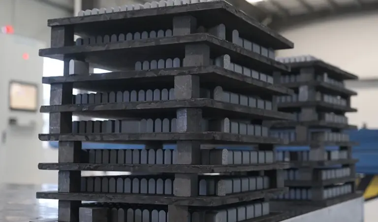
For a carbide blade replacement, keep the original condition documented until the supplier resolves the claim. A trimmed part may no longer represent what was delivered, complicating both technical review and the commercial remedy. Once the correct configuration is established, qualified personnel can install it under the equipment instructions and verify seating. Close the case with the accepted part combination so the next order does not recreate the same guard conflict.
Primary references support the specific points linked above; equipment documentation applies to its stated models.