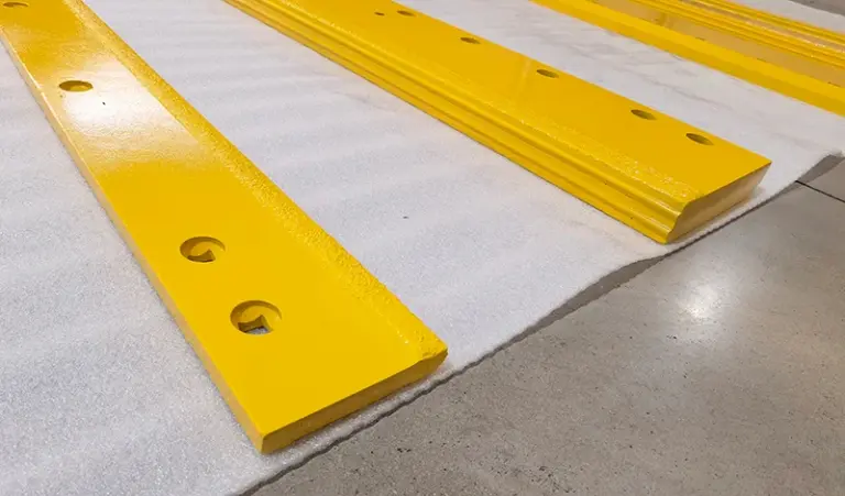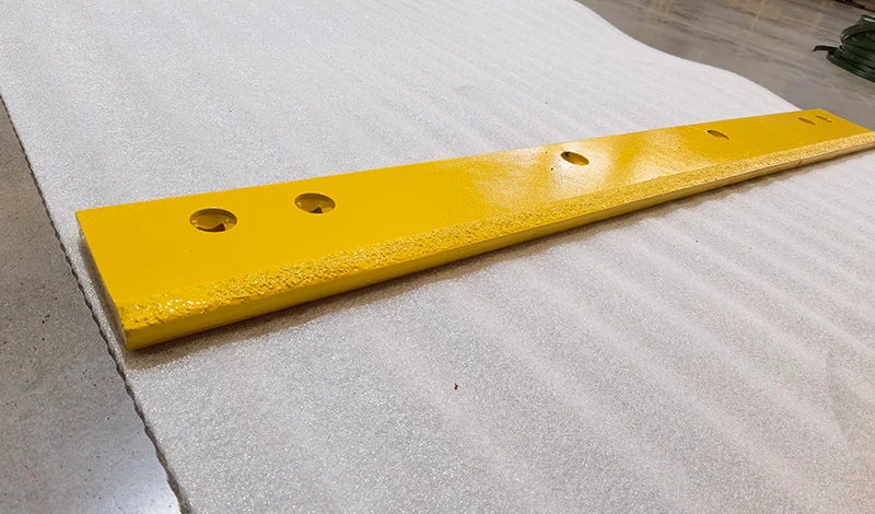
Treat the repaired rail as an unverified interface until its approved condition is established. The original blade drawing may still be correct, but it does not prove that the repaired mounting assembly still matches it.
Treat the repaired mounting interface as an unverified configuration
Find the repair record and identify exactly what was changed: a local section, a mounting hole, a seating face or another feature. Keep the repair authorization, available before-and-after photographs and the original assembly reference together. If no record exists, state that limitation rather than calling the repair an original-equipment configuration.
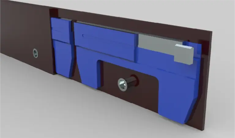
The mounting interface guide provides general context, but this enquiry is about whether a specific repair preserved the intended fit. Do not revise the blade drawing simply to match a rail whose condition has not been assessed. Doing so could turn an unresolved equipment issue into a permanent replacement-part specification.
Measure the rail separately and retain before-and-after repair records
Have qualified personnel compare the repaired rail with the controlling equipment definition under the appropriate isolation procedure. Measure the rail separately from the removed edge so damage in one cannot be hidden by wear in the other. Note where the available references are intact and where the repair prevents a reliable original-dimension comparison.
Use the relevant installation and parts documents to locate the intended assembly information. Where those documents do not provide the repair acceptance details, the repair authority or equipment manufacturer needs to determine the next review. A supplier can compare a proposed blade against stated dimensions; that comparison does not certify the structural condition or acceptability of the repaired rail.
Require repair authority and fit approval before treating the original drawing as current
There are two distinct approvals to obtain: that the repaired assembly is acceptable, and that the proposed edge matches the approved interface. Keep them separate in the record. If the repair restored the original configuration, the existing blade drawing may remain applicable. If an authorized change altered the interface, the replacement drawing and fleet cross-reference should reflect that change visibly.
A carbide blade reorder should identify the repaired machine and the configuration being supplied. Do not generalize its dimensions to untouched units without checking applicability. Close the enquiry with a documented interface disposition, not an instruction to elongate holes during installation. This approach also protects the next replacement cycle: stores can see whether the machine takes the original part, an approved variant, or remains unavailable for a standard reorder.
Primary references support the specific points linked above; equipment documentation applies to its stated models.