Do not assume symmetry or choose a datum solely because one end looks cleaner. Define the installed viewing direction, measure the two offsets separately, and have the drawing owner select the reference that agrees with the mounting assembly.
Label left and right from a defined viewing direction
Start by naming the view. ‘Left end’ is ambiguous when one person faces the front of the plow and another looks at the removed blade from behind. Add an installation sketch showing the working edge, mounting face and direction of view. Label the ends A and B if that makes the exchange clearer, then carry those labels onto photographs and the proposed drawing.
Keep the observation separate from the explanation. Different offsets might be intentional, might reflect a shortened replacement, or might include damage. A worn sample alone does not settle which explanation is correct. Note visibly altered areas without reconstructing their original position. The blade measurement guide covers the wider measurement set; this enquiry needs a specific answer about orientation and the relationship between the two ends.
Record end-to-first-hole distances independently instead of assuming symmetry
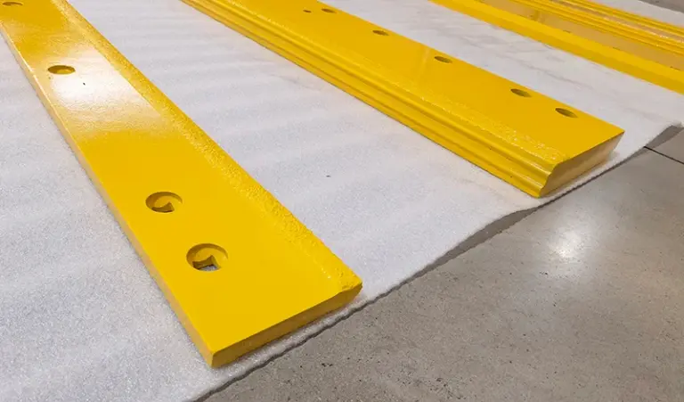
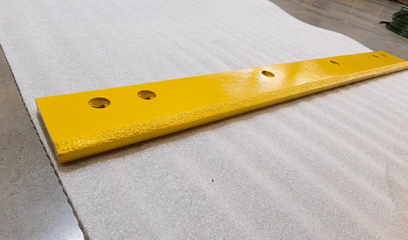
Measure each end-to-first-hole relationship independently using the agreed centre reference. Include overall length and the intermediate hole locations so the reviewer can compare both end conditions with one complete pattern. A symmetrical sketch that averages the offsets would erase the very difference that needs investigation. Where a corner is damaged, flag that reference as uncertain rather than estimating a clean edge and presenting it as measured.
Compare the removed blade with the machine-side mounting drawing. OEM document libraries are a route to the relevant parts information, not evidence that this sample is original. Look for an adjacent segment, centre joint or end guard that explains why one end may have a different interface. Ask which mounting feature is intended to locate the part. A convenient workshop reference and the approved design datum are not necessarily the same thing.
Have the responsible engineer approve the datum and matching mounting-face drawing
Send the proposed datum scheme to the responsible engineer with both measured offsets still visible. Request a marked approval showing the controlling datum, direction of increasing dimensions and treatment of the opposite end. Where the original drawing is missing, the approval should distinguish recovered design information from dimensions inferred from the old blade. Do not let a supplier’s drawing software impose symmetry by default.
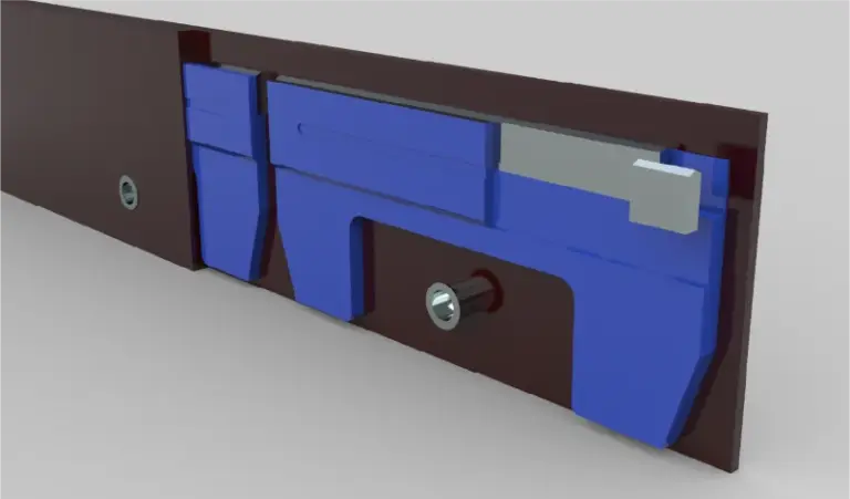
When discussing a replacement carbide edge, identify which end belongs at which installed position. Retain that orientation in the part label and inspection record. An accepted drawing should allow a different inspector to reconstruct the same end-to-hole check without relying on a phone conversation. Before release, ask one practical question: if the blade were turned end for end in the drawing, would the documented checks expose the mistake? If the answer is no, the reference scheme remains too ambiguous for ordering.
Primary references support the specific points linked above; equipment documentation applies to its stated models.