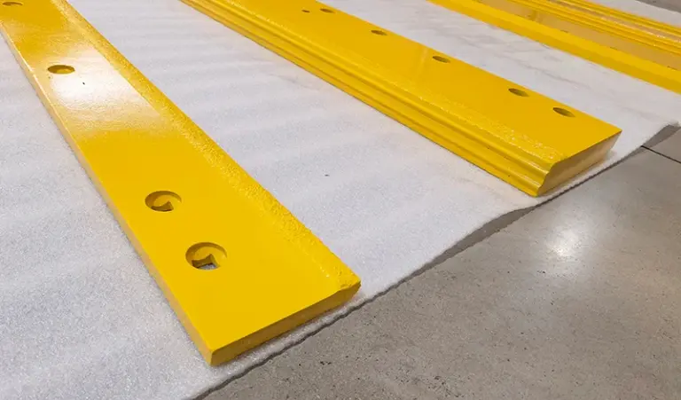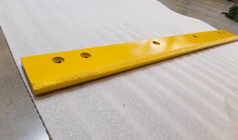
Stop the fit attempt and review the hole seat together with the specified bolt head and assembly stack. Matching hole centres does not establish correct fastening. Do not force the heads down or substitute bolts to make the mismatch disappear.
Identify hole seat geometry and the specified bolt-head form
Describe the condition with the blade and hardware identifiers attached. Does the head contact only one side of the seat, remain above a recess, or meet a surrounding part? Use clear photographs from safely accessible positions and a section sketch of the intended interface. Distinguish the observed contact from an assumed cause; a photograph cannot establish every hidden seating dimension.
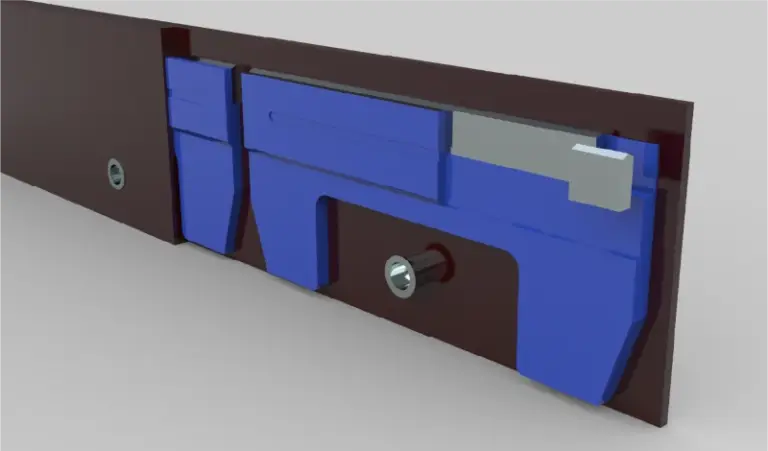
The mounting and fastening guidance gives the broader fitment context. For this enquiry, the key comparison is between the drawing’s hole-seat form and the approved head form, not merely the hole diameter. Include whether the hole is round, slotted or recessed and which face is intended to receive the head. A familiar-looking bolt is not a substitute for its specification.
Document stack thickness, orientation and head clearance without forcing hardware
Show the order of layers between the head and nut: edge, cover plate, mounting member and any specified washers or companion components. Label which faces should seat together. Record the proposed blade thickness at the mounting location rather than assuming a nominal body thickness describes the full stack. Keep any missing or changed component visible in the enquiry.
Retrieve the applicable hardware list through the OEM parts documentation. Its purpose is to identify the required fastening arrangement for the actual equipment. Do not transfer hardware instructions from another model, and do not infer approval from the fact that a different bolt can pass through the hole. Tightening an unresolved interface is not a dimensional inspection method.
Resolve the complete fastening interface against the OEM parts drawing
Ask the supplier to compare its blade seat drawing with the equipment requirement and identify the discrepancy explicitly. The resolution might concern the supplied edge, the hardware selection or an incorrect assembly assumption. Request the corrected part or an authorized disposition, including the drawing revision it applies to. Keep machining, grinding or other modifications outside the fit check unless separately engineered and approved.
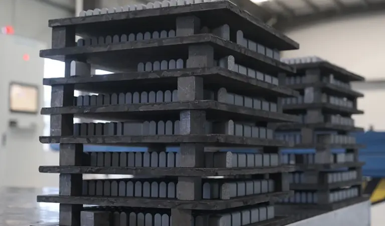
For a replacement carbide blade, confirm that the quote covers the seat geometry as well as hole spacing. Before accepting the resolution, have the qualified installer verify the complete fastening interface under the model’s procedures. The closing record should say which combination of edge, companion parts and hardware is approved. That is more useful than a note that the heads eventually went flush, which would not explain how the original mismatch was resolved.
Primary references support the specific points linked above; equipment documentation applies to its stated models.