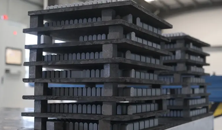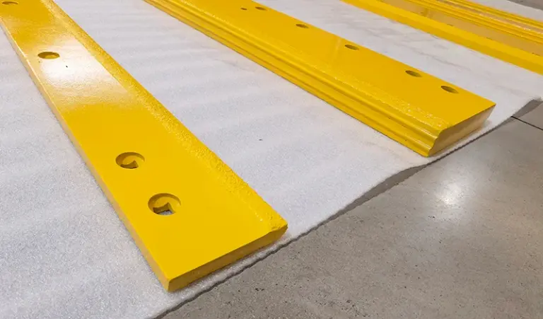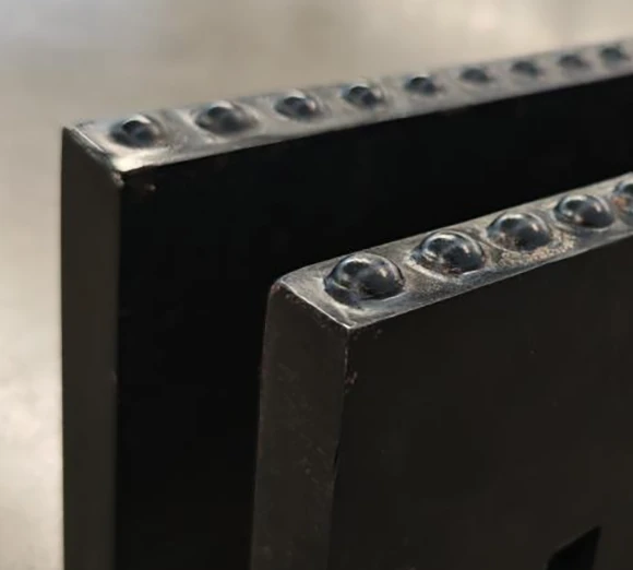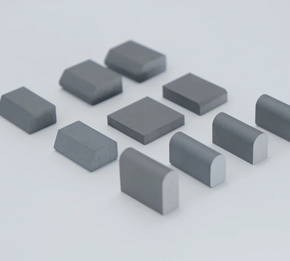
Yes, treat the radius difference as a feature requiring comparison with the controlled profile and an authorized disposition. Passing the main dimensions does not resolve a changed edge feature. Establish whether the radius is specified, whether the supplied part differs and who can approve any deviation or revision.
Compare the controlled profile including the radius feature
Identify the exact edge and its function on the drawing. Mark the radius difference on photographs of the approved reference and the delivered sample, keeping their identities separate. Check whether the sample represents a particular drawing revision or only an earlier exploratory version. A reference labelled “approved” needs an approval scope that can be verified.
Ask the inspector how the feature should be measured and reported. An oblique phone photograph can show that profiles appear different without establishing a radius value. Do not estimate a precise dimension from the image and enter it as a measured nonconformance. If the drawing does not control the feature clearly, send that ambiguity to the design authority.
The insert-profile comparison guide addresses broader shape selection. This case is a narrower change-control question: whether a delivered edge feature is consistent with the approved part, even though its overall envelope appears correct.
Review its fit and application consequence with the design authority
Give the design authority the mating geometry, intended orientation and supplied-surface information. Ask which fit, joining or working-profile requirements could be affected by the changed feature. The answer may depend on where the radius sits in the assembly; it should not be assumed harmless or harmful simply because the change is visually small.
CERATIZIT's joining guidance is relevant background when the feature lies near a joining interface, but it does not prescribe an acceptable radius for this design. Keep the review at the drawing and qualification level. Do not instruct the workshop to grind the inserts to match the sample or alter a joining process without approval.
Identify how many delivered pieces show the variant and which lots or packages they belong to. If only a few have been examined, record the inspected quantity rather than assuming the entire order is identical. Preserve an example of each observed profile with clear labels while the technical decision is pending.
Issue a documented deviation or new revision before treating the part as equivalent
The disposition should state whether the parts conform to the existing requirement, are accepted under a bounded deviation, need rework under an approved process or require replacement. If the new profile is to become standard, issue a controlled revision and specify when it applies. Do not let a single sample acceptance become an undefined permanent allowance.
Historical Clear Roads research treats insert geometry as a specification subject, but it does not decide the radius or acceptance rule for this part. The order, controlled drawing and authorized design decision remain the basis for release. If no requirement existed, resolve the new requirement transparently instead of inventing a retrospective limit.
For future carbide insert orders, include the accepted radius feature and inspection basis in the drawing package. Keep rejected or superseded samples physically distinct. The goal is a repeatable approved profile, not merely a record that someone thought two inserts looked close enough when the delivery was urgently needed.
Sources and further reading. The ordered specification and applicable equipment documentation control acceptance and service decisions.
Clear Roads 17-02: Standard Specifications for Plow Blades with Carbide Inserts (historical research; not a universal specification) ↗CERATIZIT Joining Techniques ↗