A tape-measure photograph is useful for identification and gross layout checks, but it should not be the sole manufacturing release. Confirm hole-centre positions independently and reconcile them with a controlled drawing before production.
Explain perspective, scale placement and hidden-hole limits
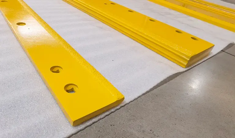
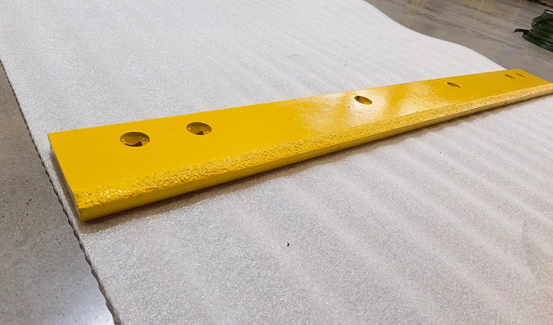
Use the picture to answer questions it can actually resolve: which side is visible, how many holes can be seen, whether the pattern changes near an end, and whether a joint or damage interrupts the layout. A photograph taken obliquely does not present every feature at the same scale. A tape lying away from the hole plane also leaves a reader guessing how its marks relate to the feature being discussed.
Take an overview as square to the mounting face as safely practical, then add labelled details of unusual holes or end features. Keep the tape’s zero and the relevant reference edge visible. Do not ask the supplier to infer a hidden hole from a repeating pattern. The bolt-pattern verification guide is useful for the wider drawing pack, but the purpose here is to separate visual evidence from dimensions authorized for manufacture.
Request an orthogonal labelled overview plus independently measured centre positions
Provide a companion list of measured centre positions from one identified datum. State the unit system and which features were inaccessible, damaged or obscured. Link each entry to the photograph with a hole number. This lets the supplier question a particular location without translating between an unlabelled image and a sketch. Do not replace a difficult measurement with an image-based estimate unless it is explicitly marked provisional.
A scale in a picture does not by itself establish a defensible measurement process. Measurement traceability guidance addresses calibration and uncertainty; a tape’s presence is not proof that the photographed view resolves the required fit. The responsible reviewer should choose a method appropriate to the drawing limits. Where the buyer lacks the equipment or access for that method, a physical sample assessment or qualified inspection may be the better next step.
Use photos to resolve identity and ambiguity, not as the sole manufacturing release
Ask the supplier to return a proposed pattern drawing with every photo-derived assumption marked. Compare its hole count, end offsets, mounting-row position and exceptional features against the independent observations. Keep the approval separate from the original image submission: ‘photos received’ and ‘drawing approved’ should be different statuses. Otherwise a helpful preliminary exchange can accidentally become the shop’s only specification.
For a carbide blade quotation, photographs can support the initial discussion while the fitment basis remains open. Let the supplier identify exactly which dimensions prevent a firm proposal. Release manufacture only when those points have a documented answer and the complete mounting interface has been reviewed. If the photo appears inconsistent with a measured list, investigate the view, reference and transcription; do not simply select the version that looks more convenient. The useful outcome is a traceable pattern, not a prettier photograph.
Primary references support the specific points linked above; equipment documentation applies to its stated models.