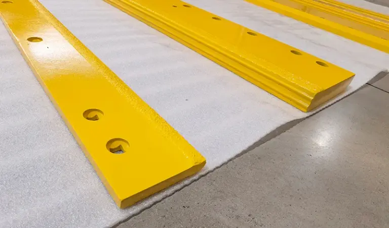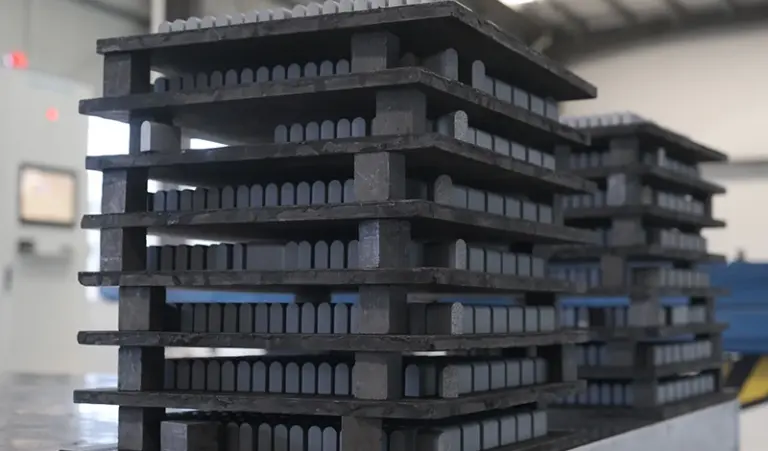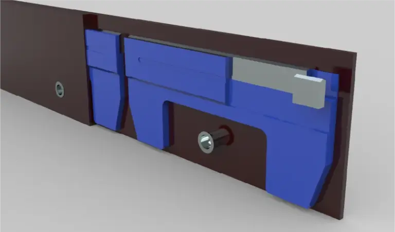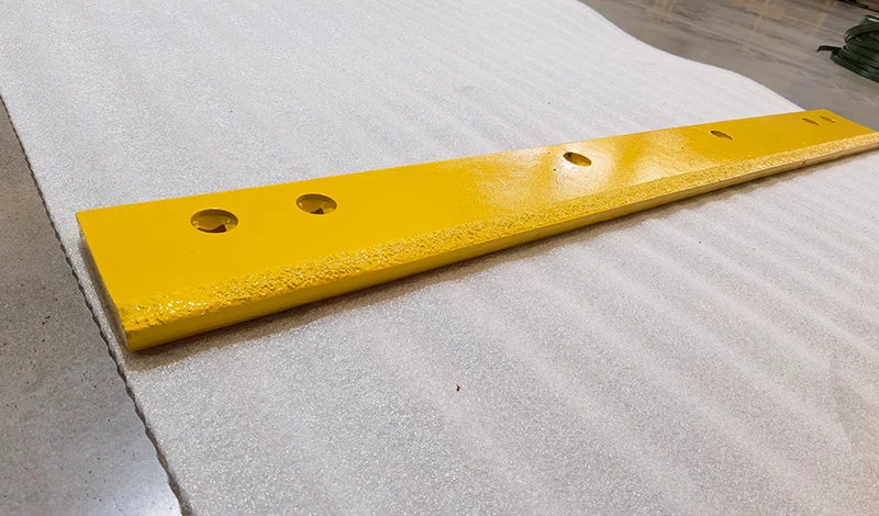
Show the complete layered assembly in section. The edge, cover plate, mounting member and specified hardware must be reviewed together; matching the loose blade’s outline does not establish seating, engagement or clearance.
Show every layer and its seating face in section
Draw the layers in their installed order and label the face each component contacts. Include the cover plate identifier and any companion parts that the approved design requires. Do not use a generic rectangle for the cover if its profile affects the interface. Mark the section location on the overall assembly so the supplier knows which region it describes.
The carbide-and-cover pairing guide provides broader context. This enquiry should focus on whether the proposed edge preserves the existing approved stack. Ask whether the quote assumes reuse of the current cover plate or supply of a different one. A changed assumption can alter the package even when the edge line item appears unchanged.
Check bolt engagement and head clearance through the approved hardware specification
Review the mounting-land thickness, hole seat and hardware arrangement against the model-specific specification. Use the OEM document library to locate the relevant assembly information where available. Do not select a longer bolt simply because the proposed stack looks thicker, or transfer an engagement rule from unrelated equipment. Hardware suitability belongs to the complete approved fastening design.
Include the locations where the cover or head could contact adjacent features. If a photograph hides the seating surfaces, say so and request a clearer approved section instead of inferring the interface. Keep measured current conditions separate from the intended dimensions, particularly when an old cover plate is worn or distorted. Reusing it is a condition to review, not a default proof of compatibility.
Approve the assembly stack rather than the edge dimensions in isolation
Ask the supplier to identify the exact edge-and-cover combination it proposes. The responsible equipment reviewer should resolve any difference in stack, seat or hardware before the buyer releases production. If only the edge is being replaced, record the companion components assumed serviceable and applicable. That makes the fitment claim bounded and reviewable.
For a replacement blade quotation, attach the assembly section to the part drawing and keep both revisions on the order. At installation, qualified personnel should follow the equipment procedure and stop if the stack cannot seat as defined. Acceptance should describe the approved combination, not merely the fact that all bolts entered. This protects future reorders from losing the cover-plate requirement when the loose blade drawing is copied into a purchasing system.
Primary references support the specific points linked above; equipment documentation applies to its stated models.