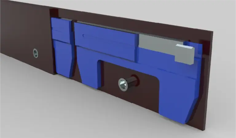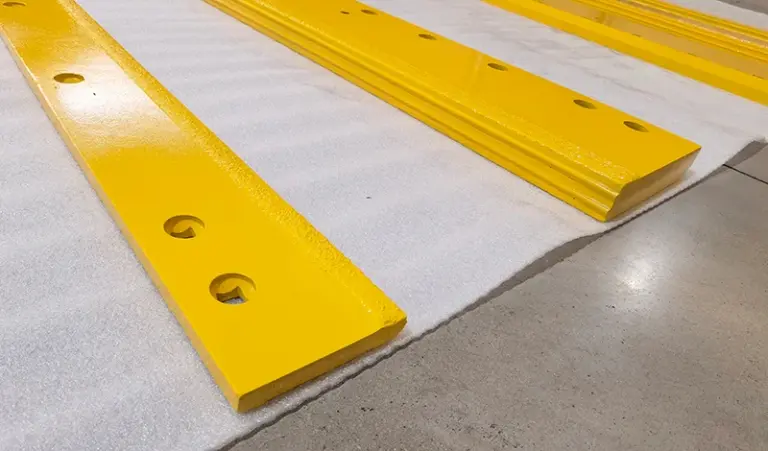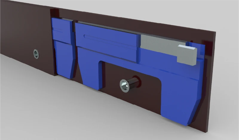
Show the retained segment and all mating clamp interfaces in their approved orientation. Identify the mounting and retention geometry separately from material properties, and do not infer a clamping compression value from the worn assembly.
Identify the clamp, retained segment and mating steel interfaces
Begin with an installed section showing the segment, clamp, carrier and relevant steel mating features. Label each component and mark the section location on an overall view. Include the part identifiers for the retained segment and the reusable clamp. A loose-segment drawing cannot explain which surfaces locate it or which interfaces retain it.
The rubber-flex segment installation guide provides the broader context. This enquiry needs a clear definition of the existing assembly, not a new clamping design. Ask the drawing owner which features are controlling and which views are illustrative. Keep any unclear or inaccessible interface marked open rather than drawing an apparently complete section from a single photograph.
Record clearances and orientation from the approved design without inventing squeeze values
Show orientation, seating relationships and approved clearances from the controlling design. Do not estimate an intended squeeze from the visible deformation of a used rubber component. The supplied segment’s free-state geometry and its installed condition should be distinguishable in the review. If the original retention definition is missing, ask the equipment authority how it can be recovered.
Use the relevant equipment documentation to identify assembly-specific installation requirements. The blade supplier can review whether its proposed segment follows the stated drawing, but that does not authorize a changed clamp or a different retention method. Avoid specifying a universal torque, gap or compression percentage from a generic product description.
Separate segment supply approval from approval of the complete clamping assembly
Separate the approval of the segment from approval of the whole clamping system. The quotation should identify whether the supplier is providing a component to your approved drawing or proposing a complete assembly. A material description, including rubber hardness or carbide designation, cannot resolve an undefined retention interface.
For a rubber-flex blade enquiry, include the section and the companion-component references with the requested quantity. Have the supplier mark deviations and assumptions before release. A qualified installer should compare the delivered components with the approved configuration and follow its instructions. Keep the final approved section in the replacement record so future segment orders do not gradually lose the clamp details that made the original enquiry workable.
Primary references support the specific points linked above; equipment documentation applies to its stated models.