One controlled drawing can cover both hands only if it defines each configuration unambiguously. Otherwise use separate drawings and part identifiers. A mirrored outline alone does not establish the correct hole seats, end interfaces or insert orientation.
Define handedness by installation position and viewing direction
Define left and right from the installed equipment’s viewing convention, and show that convention on the drawing. Include the mounting face and working edge in the view. A removed edge photographed from behind can reverse the apparent hand, so loose labels are not enough. Give each wing position a clear assembly reference.
Use wing-edge fitment guidance for the surrounding assembly considerations. The narrow decision here is document clarity: could a supplier, inspector and stores person identify the same hand without seeing the original email? If not, the single-file arrangement needs additional views or separate controlled identifiers.
Compare end profiles, countersinks and insert orientation, not only length
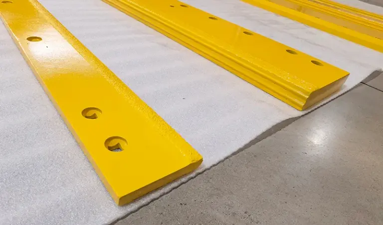
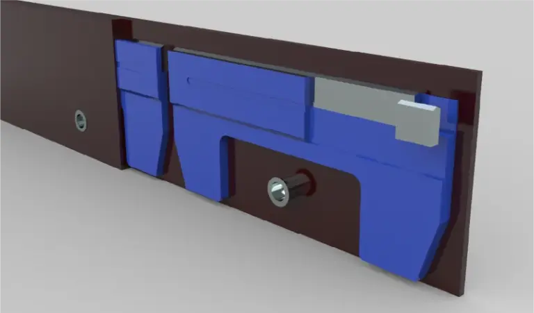
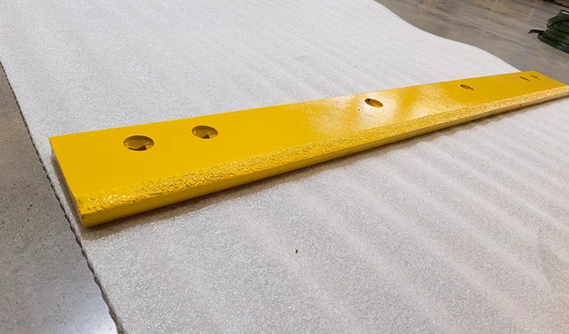
Compare more than overall length and the outside shape. Check the end profiles, hole pattern, recess direction, seating faces and insert arrangement against the approved design. A geometric mirror may reverse a feature that is meant to remain on the same mounting face. Do not assume CAD mirroring carries the intended functional orientation automatically.
Locate the relevant assembly views in the model-specific documentation. They are useful references for installed position, but they do not approve a new supplier’s mirrored part. Ask the drawing owner to show both permitted configurations and their distinguishing features. If the two edges are actually identical and approved for either position, record that explicitly rather than relying on visual similarity.
Use separate identifiers or an approved mirrored drawing with unambiguous labels
A shared drawing should contain a configuration table or equally clear callout connecting each part identifier to its views and quantity. Separate drawings are preferable when a single file becomes easy to misread. Whichever route is chosen, labels on the delivered parts and packaging should use the same handedness convention as the order.
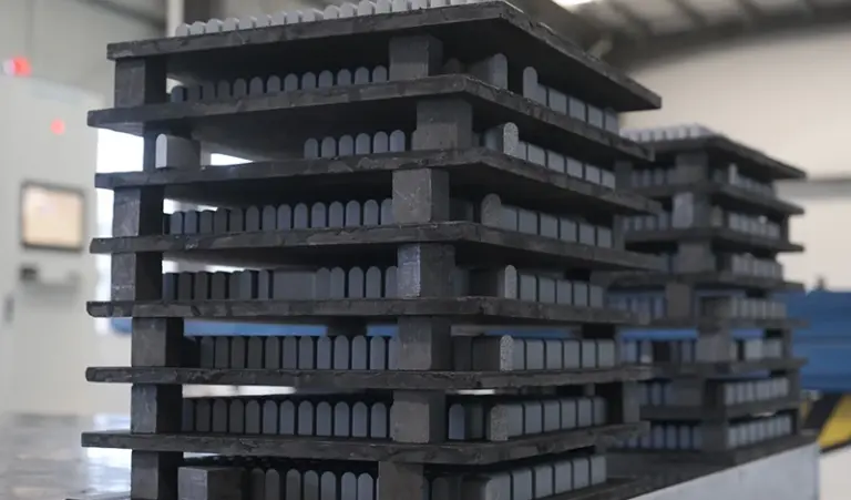
When obtaining replacement carbide edges, ask whether the quoted quantity means individual edges or a left-and-right set. This commercial distinction can otherwise survive a technically correct drawing review. Have inspection verify the distinguishing features before the set is issued to a machine. The objective is not a particular number of drawing files; it is a release package that cannot silently produce two examples of the same hand when the assembly needs a pair.
Primary references support the specific points linked above; equipment documentation applies to its stated models.